My college capstone was a DIY recreation of the Neumann KU 100 binaural microphone. I was able to create a fully functioning dummy head microphone with a 10Db switchable pad flexible ears mechanical diffuse field equalization and more.
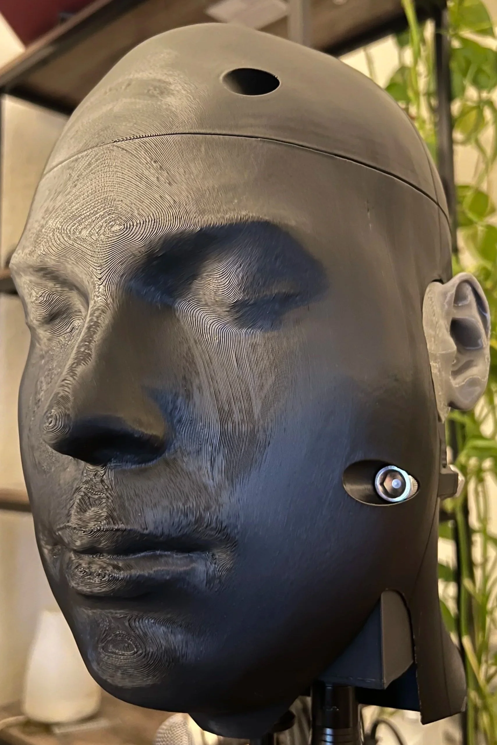
Dummy Head
Binaural Test audio
Audio demonstrating the 3D nature of the binaural microphone
Binaural Room Mic
Dummy head positioned where by the room mic
Binaural Drummer
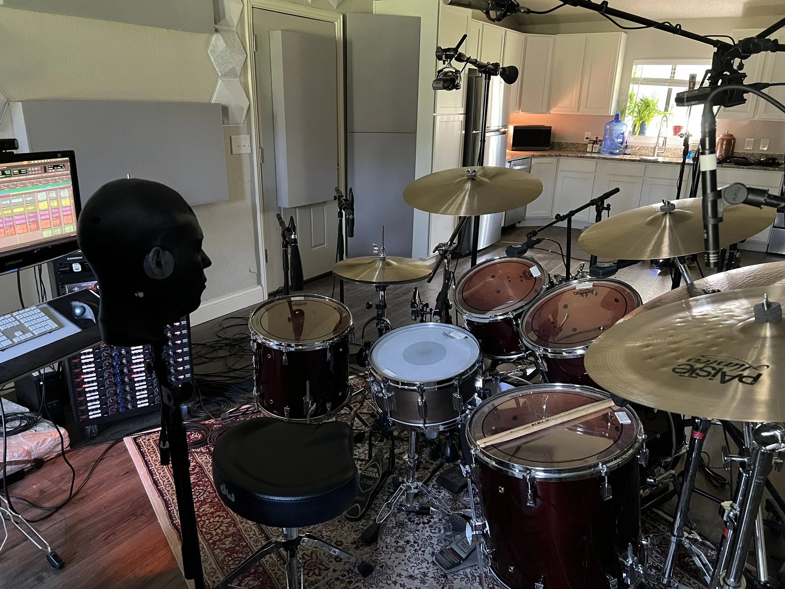
Dummy head positioned where the drummers head would be
Binaural Band Mate
Dummy head positioned where a band member would be relative to the drums
Research and Design
Capsules/Preamps
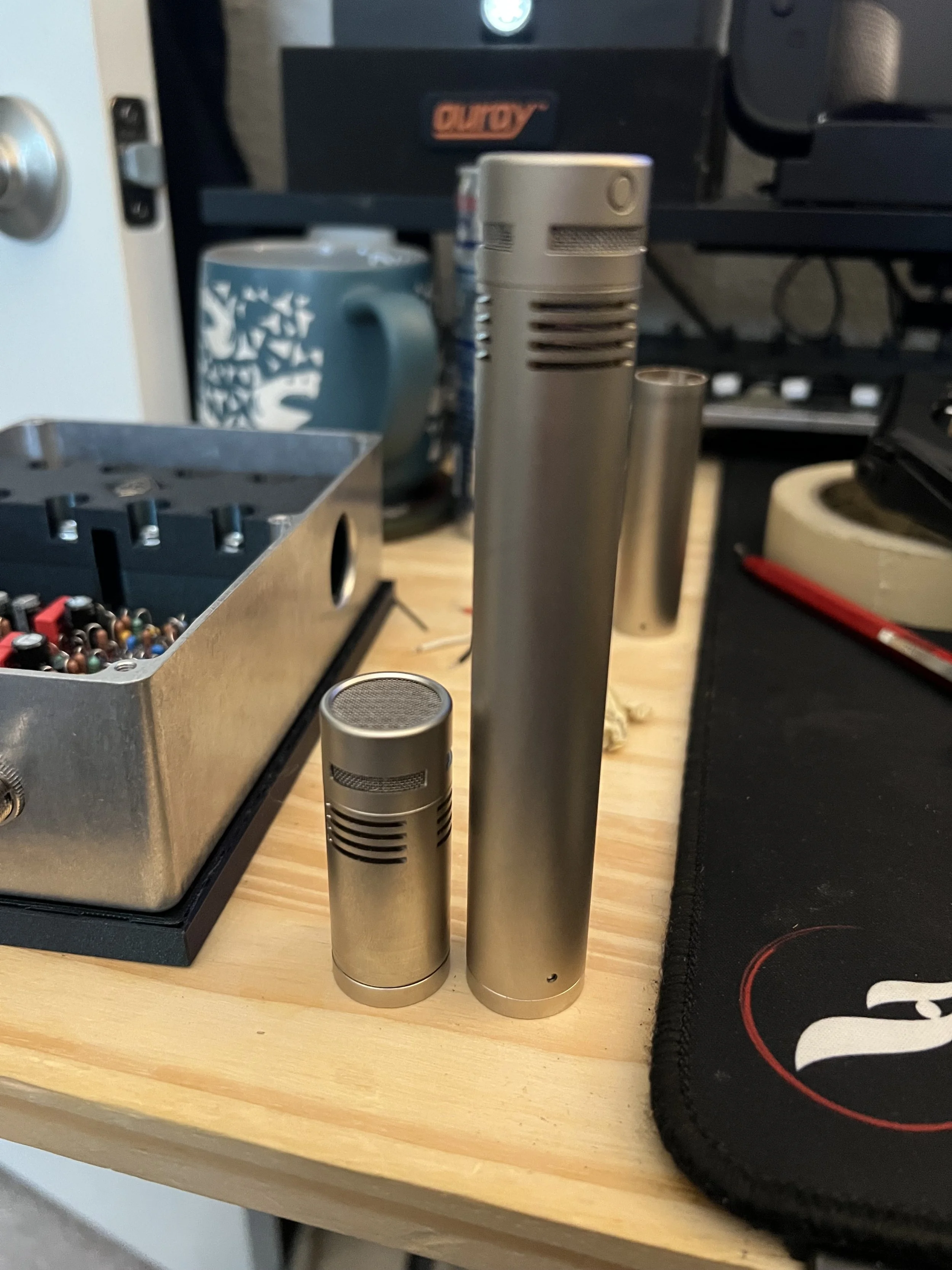
While most Binaural heads use small 5mm omni capsules to accurately capture the ear canal the KU 100 uses a much larger 22 mm omni capsule. This gives it a much higher signal to noise ratio and allows for better loudspeaker reproduction. The downsides of this size come from fitment and smooth air flow from the much small ear canal affecting frequency response. To reproduce the KU 100 I used a stereo pair of MicParts (Roswell pro audio) SDC pencil condensers. These microphones are 22mm in diameter with an omni pickup pattern. and the internal preamp is based on the transformer less CM5C Schoeps circuit.
10 Db pad
The KU 100 has a single switch for a stereo 10Db pad. this allows for recording of higher signal sources without overloading the circuitry. there are a number of simple ways to create a 10Db pad. many condenser microphones use a resistor and capacitor to ground. some create a pad by connecting the phase flipped outputs using resistors. Thankfully in the build instructions for the SDC preamps it states that adding a capacitor in parallel with the preamp coming out off the capsule you can change the effective capacitance of the mic capsule. this results in lower signal reaching the preamp and creates a pad. according to the instructions a 150pF axial styrene capacitor will result in a ~10Db pad. for my build I was able to acquire 163pF Siemens axial styrene capacitors and a 100V rated switch to connect the grounded capacitors to the capsules signal wire. this results in ~10Db switchable stereo pad.
Pinnae/Ear Canals
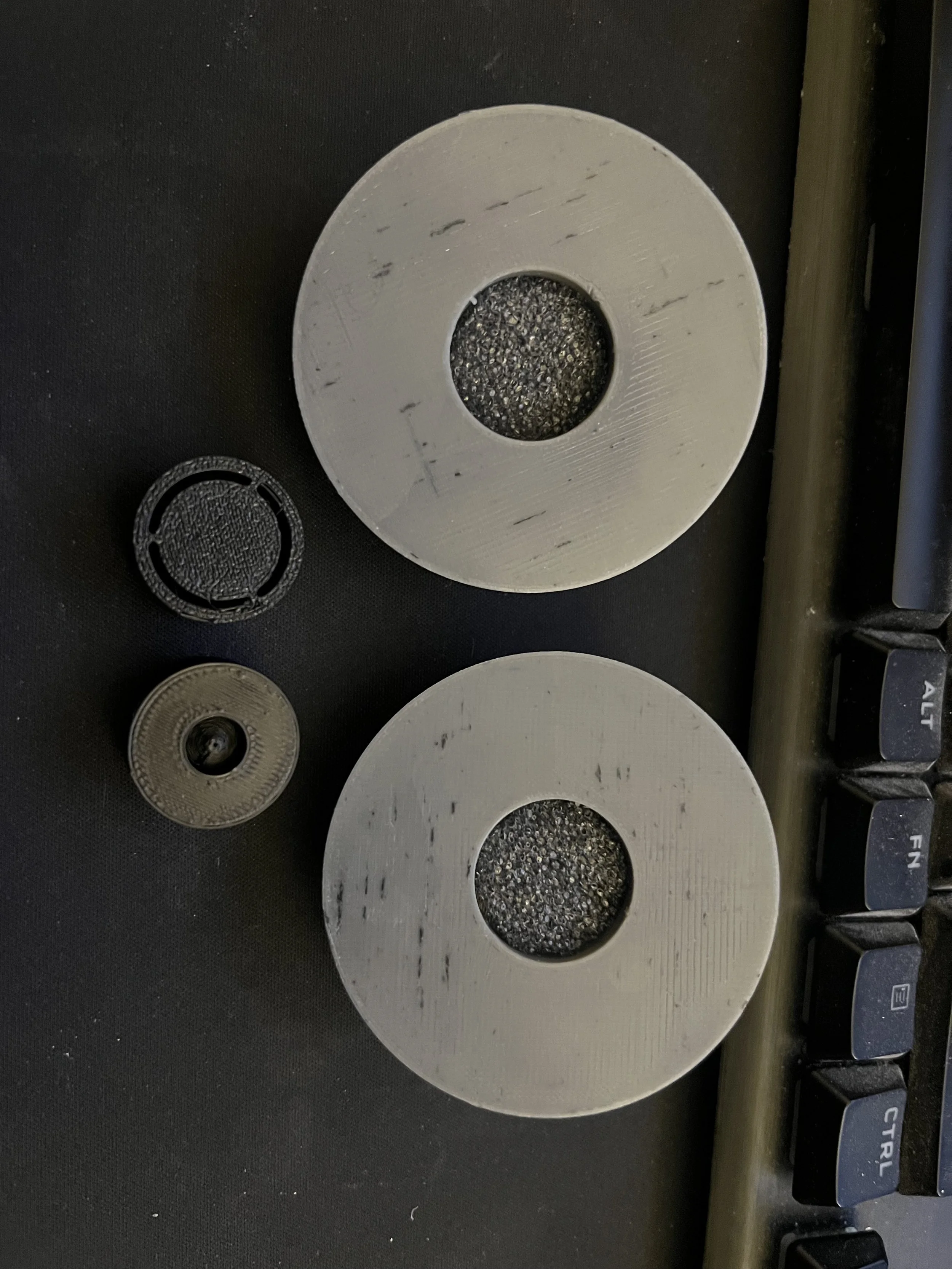
For Binaural recording Neumanns research shows that having the full pinnae and and the first 5 mm of the ear canal modeled provided almost all of the spatial encoding information. having full ear canals does provide a more accurate Binaural recording but it substantially reduces the quality of loudspeaker reproduction. this downside would make the microphone much less versatile. Almost all commercially available binaural microphones use this methodology and only mold the first 5mm of the ear canal. The pinnae and ear canal are also responsible for the microphones pickup pattern and frequency response since the KU 100 and my recreation both have 22mm capsules which are much larger than the ear canal there is a substantial affect on the polar pattern and frequency response. According to Stephan Peus (The lead designer for the KU 100) Binaural microphones should be diffuse field equalized to achieve the most accurate capture of the room they are in. this was change between the KU 80 and the KU 81 which was achieved by adding a conical tube to expand the smaller diameter of the ear canal up to the larger diameter of the microphone capsule. the centre cone of this was made hollow to act as a Helmholtz resonator to help the frequency response of the microphone which was tuned based of of their finding with the protoype they made where they could tune the Helmholtz resonance. Since my head, ear shapes, and microphones parts are different from Neumanns I couldn’t perfectly recreate this however I was able to create an approximation which significantly improved the frequency response, sensitivity, and stereo imaging. In addition to this Stephan Peus notes that for the KU 81 they made a pair of perfectly symmetrical ear pinnae and canals to make the binaural head more universally accurate. To get the most accurate ear shape I could imagine found online models of ears based off of the IEC 60318 submission for artificial ear testing and used those to build my microphones ear assembly.
Frequency response and equalization
A binaural head should be diffuse field equalized (flat frequency response in a live room). since I do not have the resources to properly test and engineer mechanical solutions. I will be recreating approximations of Neuamnn’s designs and doing final adjustments using linear phase MS and stereo EQ digitally. This will allow me to tweak the heads response and get it as close as possible to the KU 100.
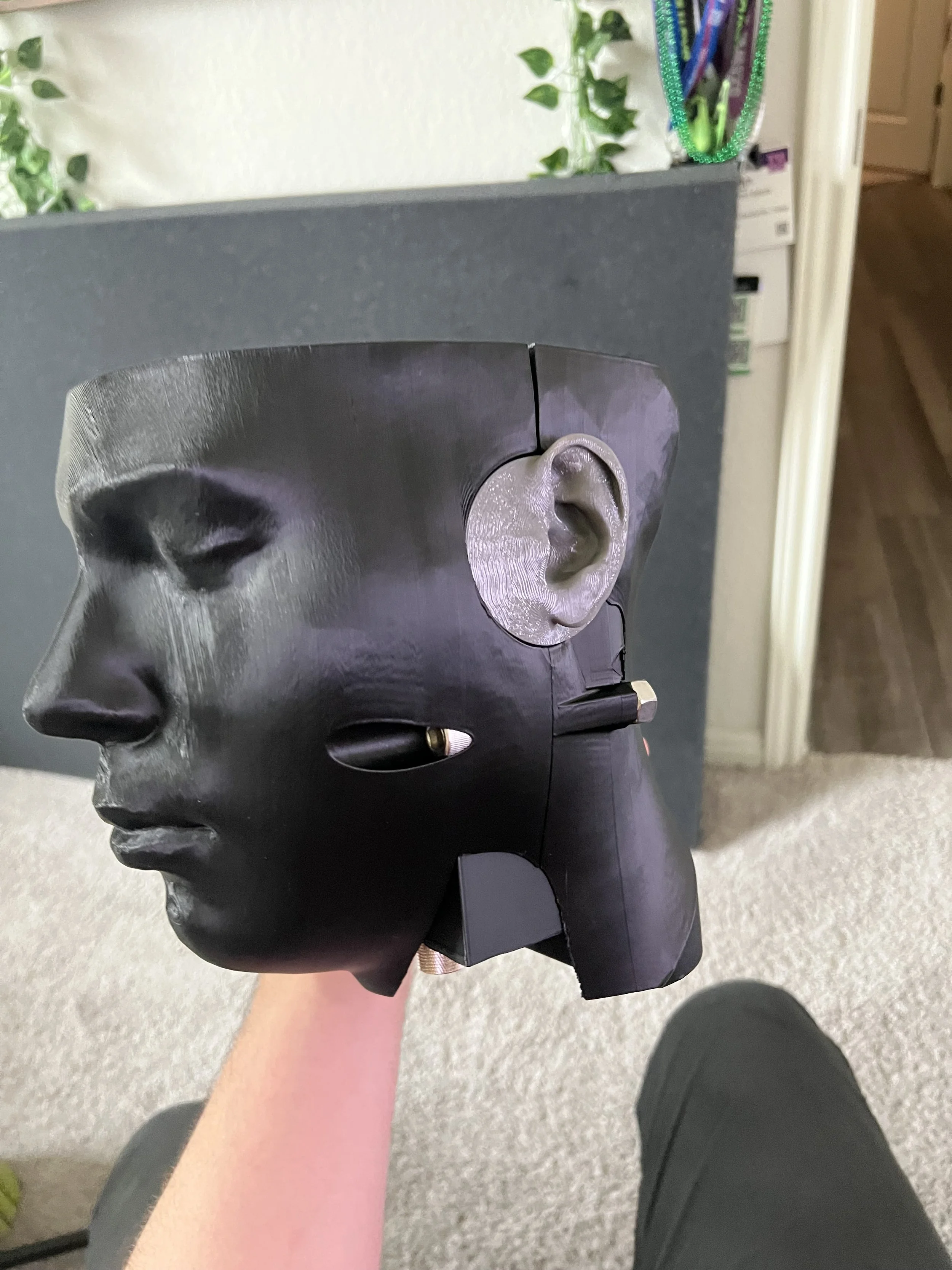
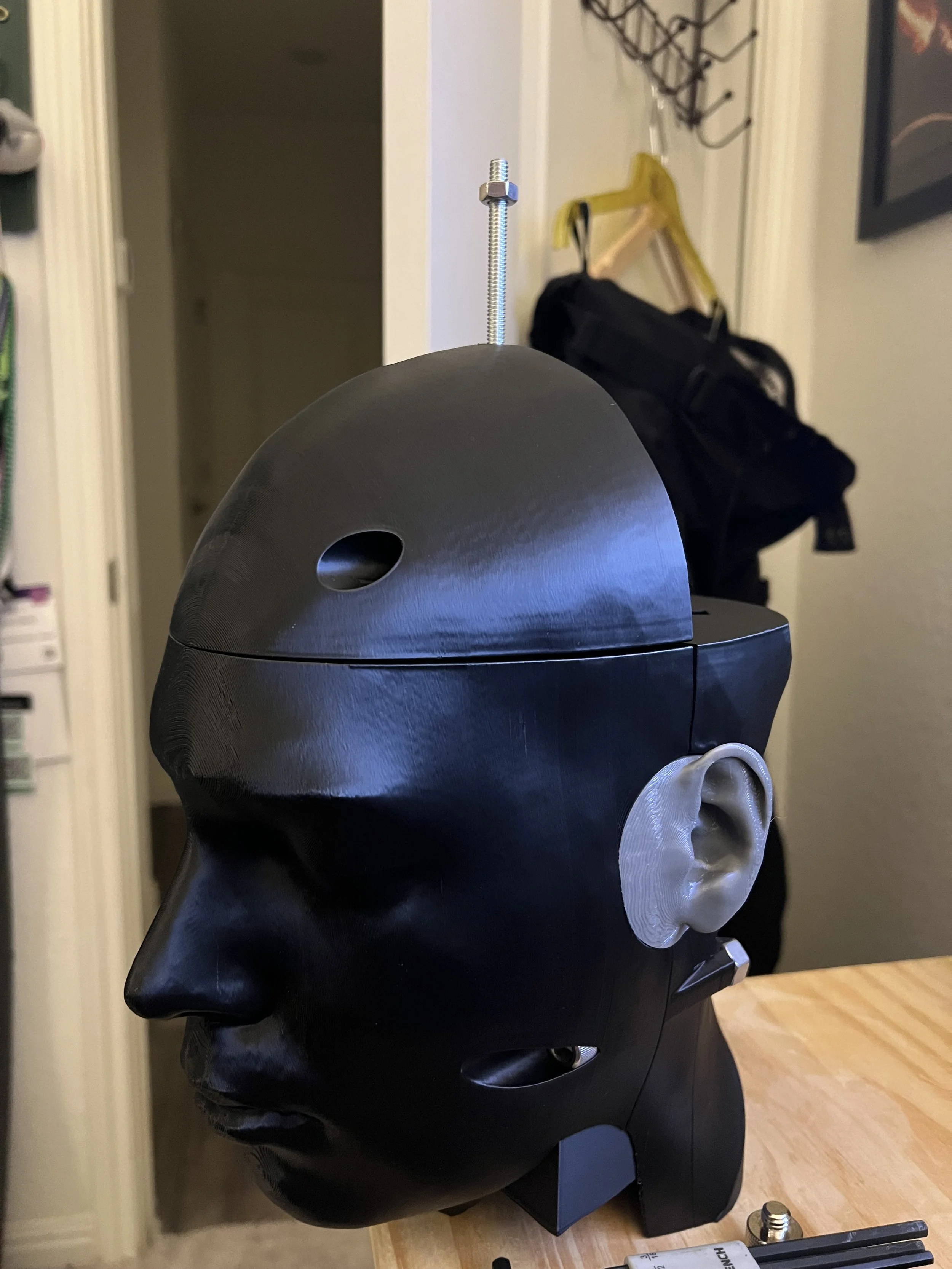
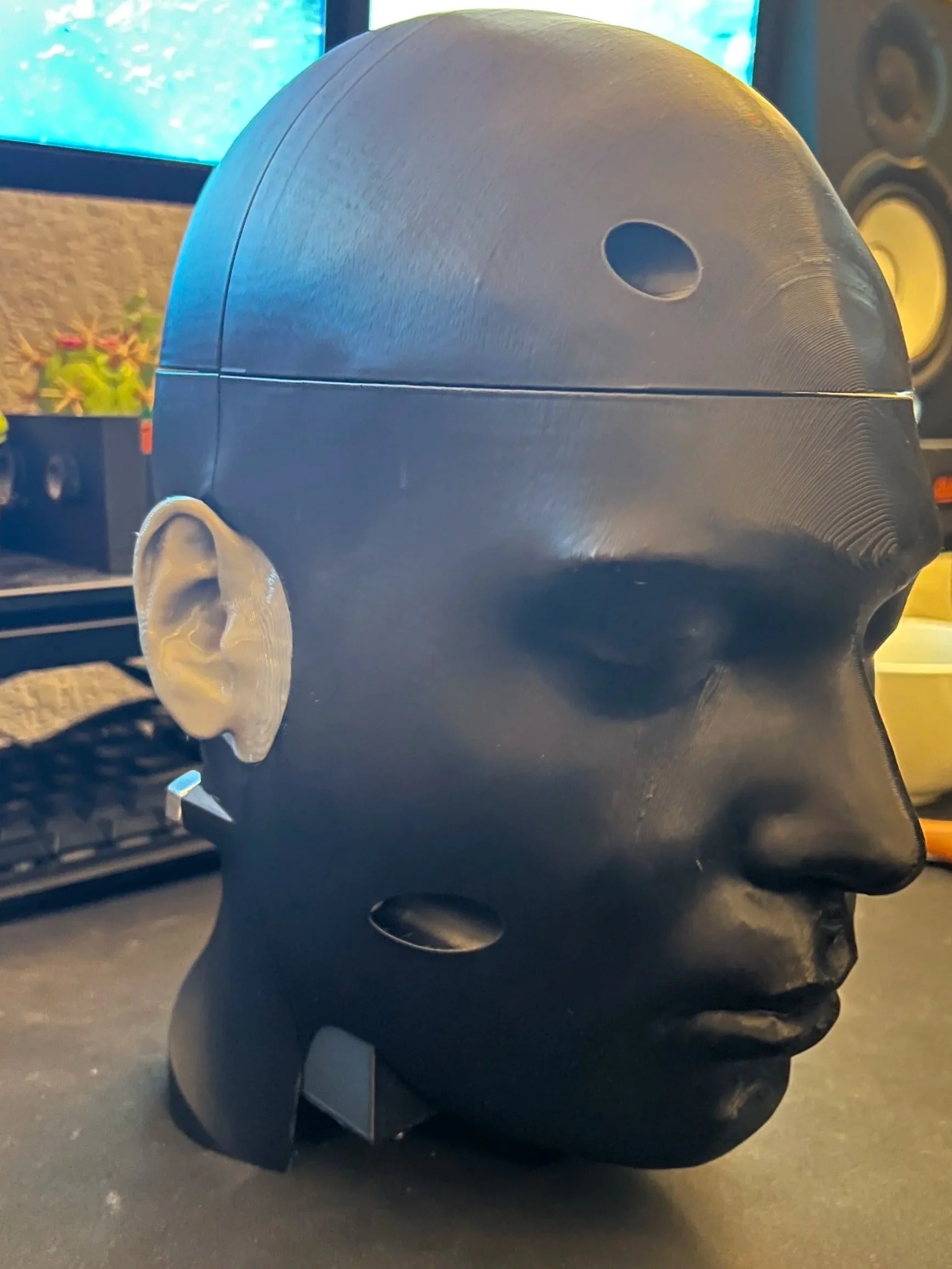
Head
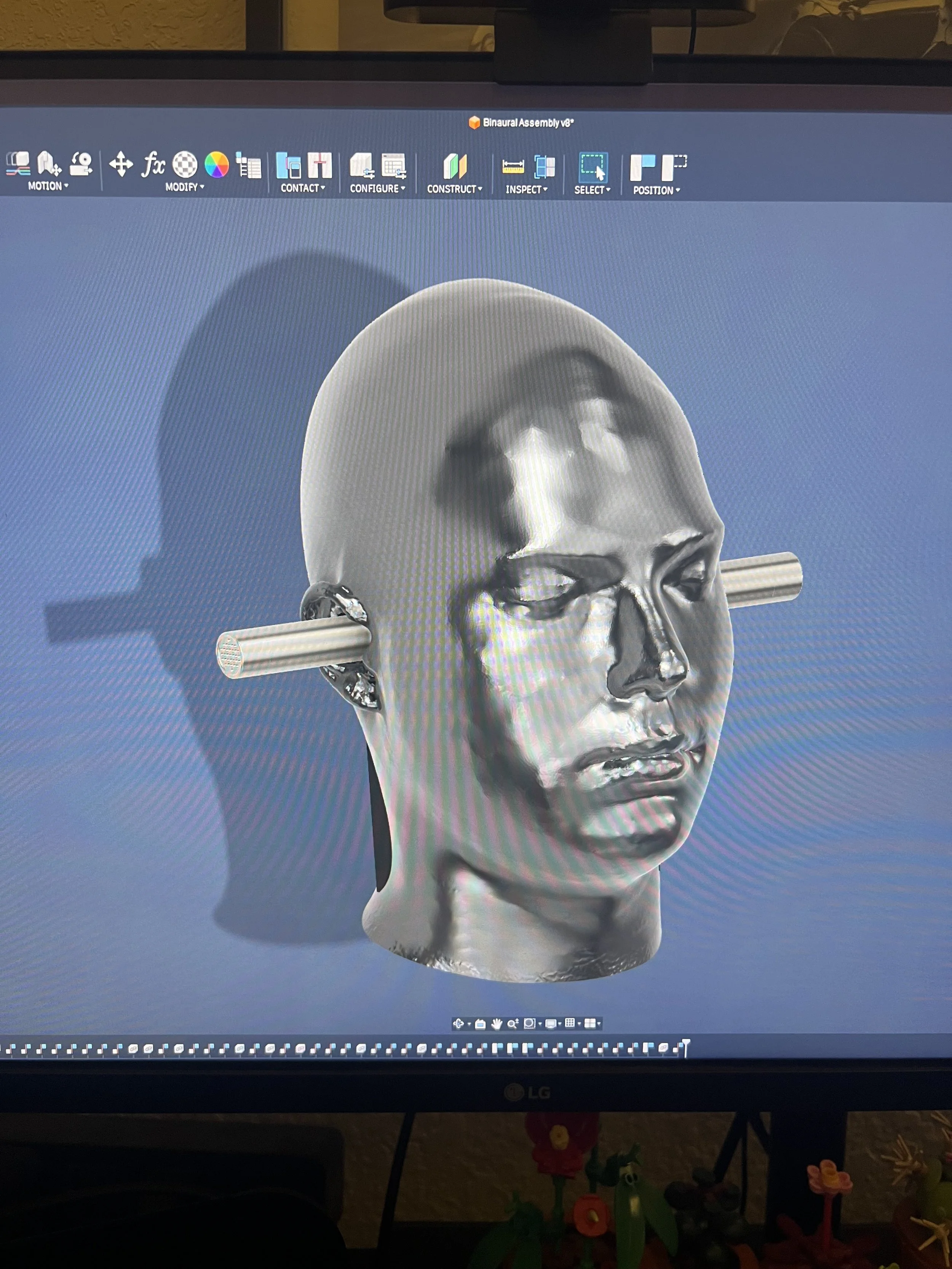
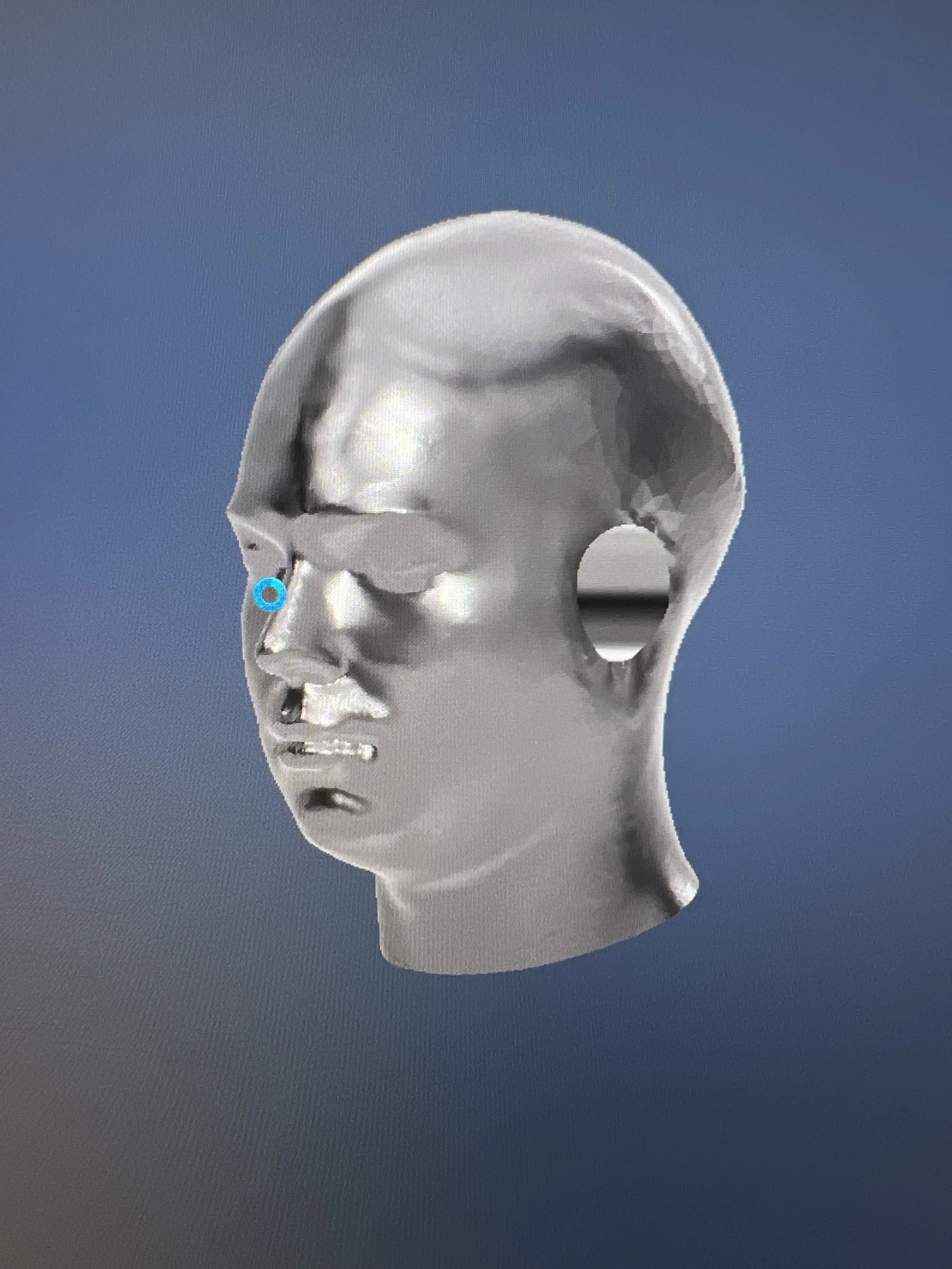
Similar to the Ear pinnae and canal it would be ideal to have a perfectly symmetrical head. I was unable to find any online models of a human head that I could use for this project. So for my head I used a 3D scan of myself. this scan was done using an Ein-Scan Rigil and had 1 million vertices and triangles when completed. Using fusion 360 I was able to smooth clean up the head and modify it so that it would fit all of the microphone components inside. This design choice also allows me to print new head shapes in the future and swap the shell without changing any of the internals. this allows the Binaural Microphone to be either a T bar style or a full Dummy- head style microphone.
EMI
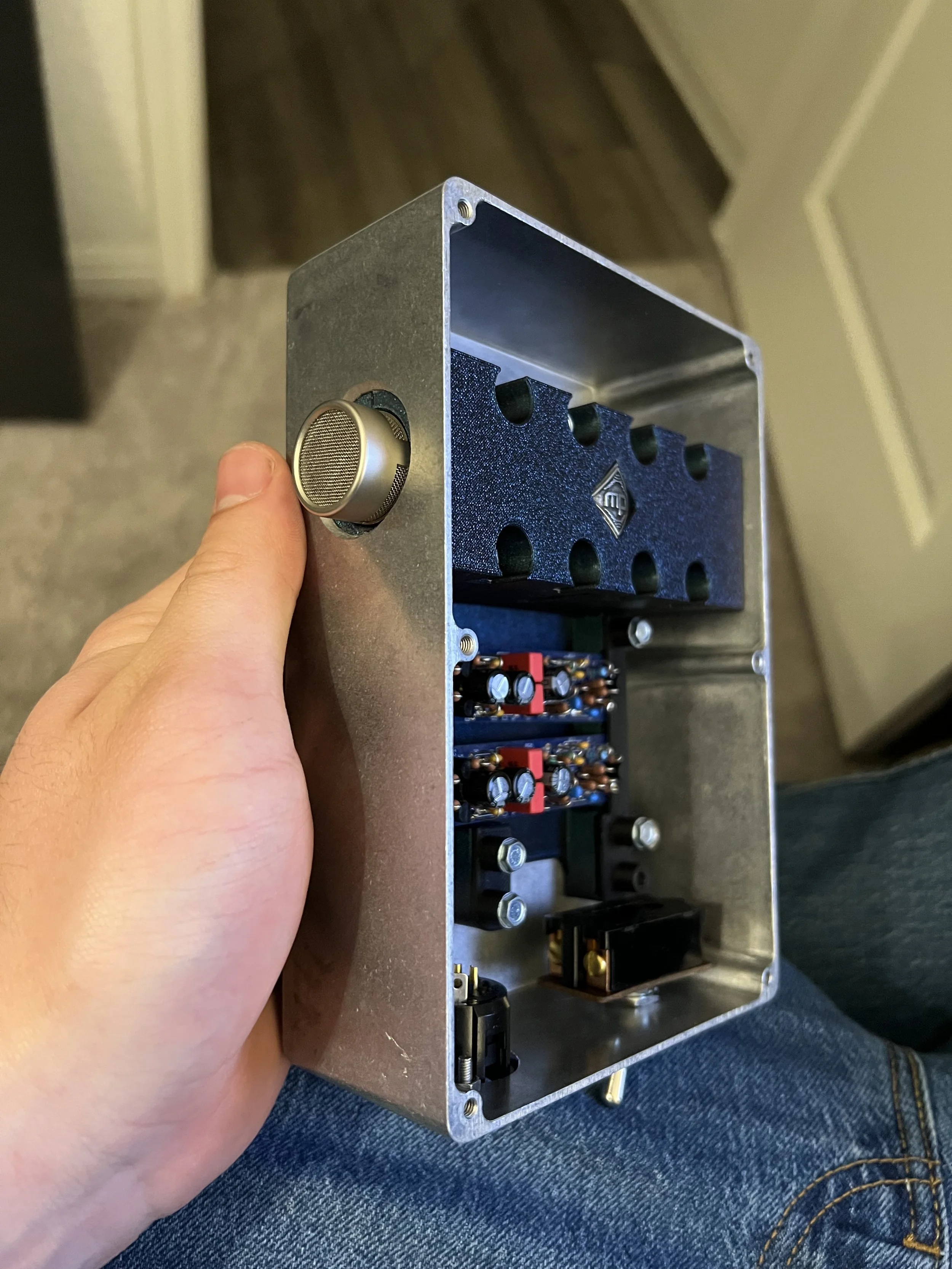
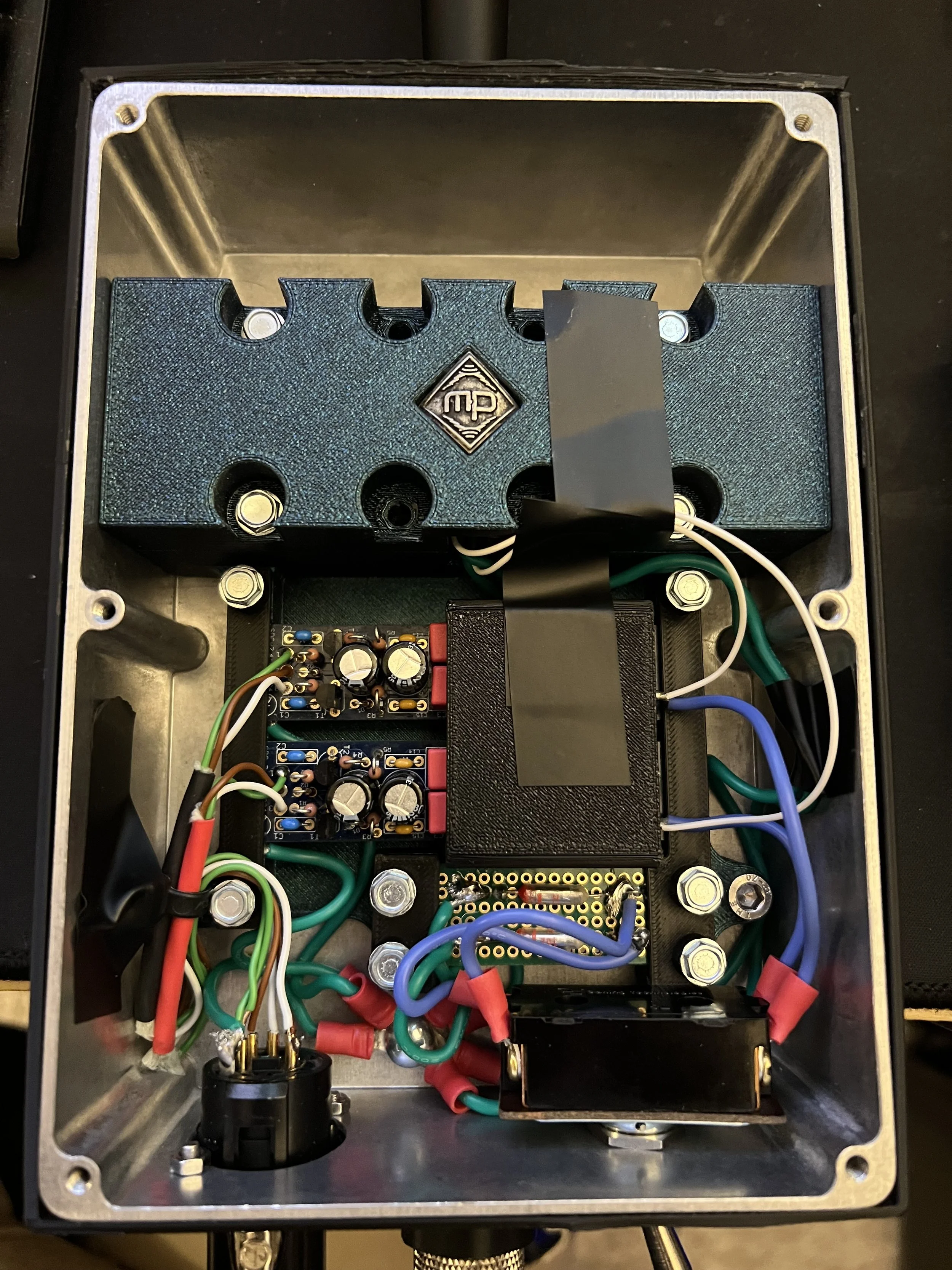
To minimize EMI I housed all components in a metal box and connected all ground to a single bolt. this made the entire box an EMI shield removed any issues.
High Pass filters
the KU 100 has a switchable HPF of 12db/octave at 50Hz and 150Hz. this slope tells us that the HPF circuit being used is a second order circuit. looking at other Neumann microphone schematics they consistently use multiple active components to achieve a 2nd order circuit. because these microphones require phantom power you can’t use a first order RC or RL circuit because it will either block the phantom power or short it to ground. this meant that to implement any HPF’s I would need a complete understanding of the preamp circuitry and how to modify it to create the circuit. Because of this level of complexity and the time required the high pass filters were cut from the spec sheet to minimize complexity and meet the deadline.
Power
Condenser microphones require DC power to power the internal preamp and get signal from the capsule. normally this is achieved through 48V phantom power supplied form your board. some microphones (the KU 100) have internal batteries to supply power in remote locations. the KU is also unique in that it will accept power from an external power supply via a switch. Most microphones don’t actually require the full 48V to function. this is how battery packs work. almost all condensers will function with a nominal voltage of 9. the KU 100 uses 6 AA Batteries in series to achieve this voltage. the downside of using low voltage power is increased electrical noise and a reduction in maximum SPL. This battery pack supplies the power in an identical fashion to phantom power from a board. by using an RC circuit to block the voltage from going down the cable and supplying positive voltage to pins 2 and 3 of the microphone circuit you give it power. Because the voltage is lower you do have to adjust the values of the Resistor and capacitor of the RC circuit to minimize impedance issues. While this would have been relatively simple to implement do to space constraints and time the internal battery supply was cut from this project as well.
Materials
The KU 100 itself is made out of a custom synthetic material meant to simulate the acoustics of a human head. unfortunately I do not have access to this material or the ability to manufacture it. with this the most important part of the binaural head is not the internal acoustics but the external reflections. My resources mean that I will need to 3D print the head out of PLA which should have a similar overall density to the solid material of the KU 100. the KU 100 uses silicone cast ease to reproduce the quality of human ears. I printed mine out of TPU a flexible plastic which is stiffer than silicone and not as accurate.
All sources and research information is provided at the bottom of this webpage.


Wiring and Build
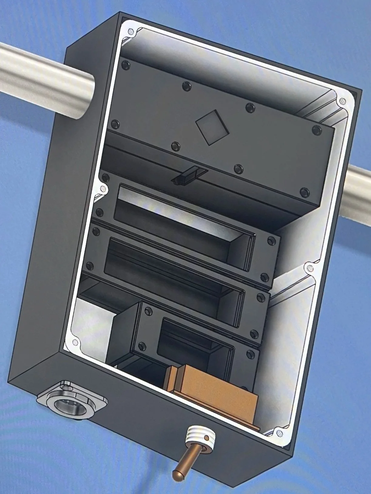
3D design
to design all of the components and make sure they fit before purchasing any I build the whole microphone in Fusion 360. this allowed me to play with different setup and designs before committing to anything. unfortunately the complexity of this project made it to where my computer could only load about 40% of the model at a time. this made it rather difficult to accurately split the shell into 4 pieces for 3D printing.
Wiring
The wiring of the microphone was relatively simple thanks to the instructions provided with the SDC kit. the modifications made were the separation of the nose cone and PCB (done with a mil-spec silver coated copper wire) and the addition of the blue pad wire to the input terminal.
3D Printing
due to the number of custom components and shapes 3D printing was the only option to manufacture this project every piece is printed in PLA using metal hardware for connections and assembly.
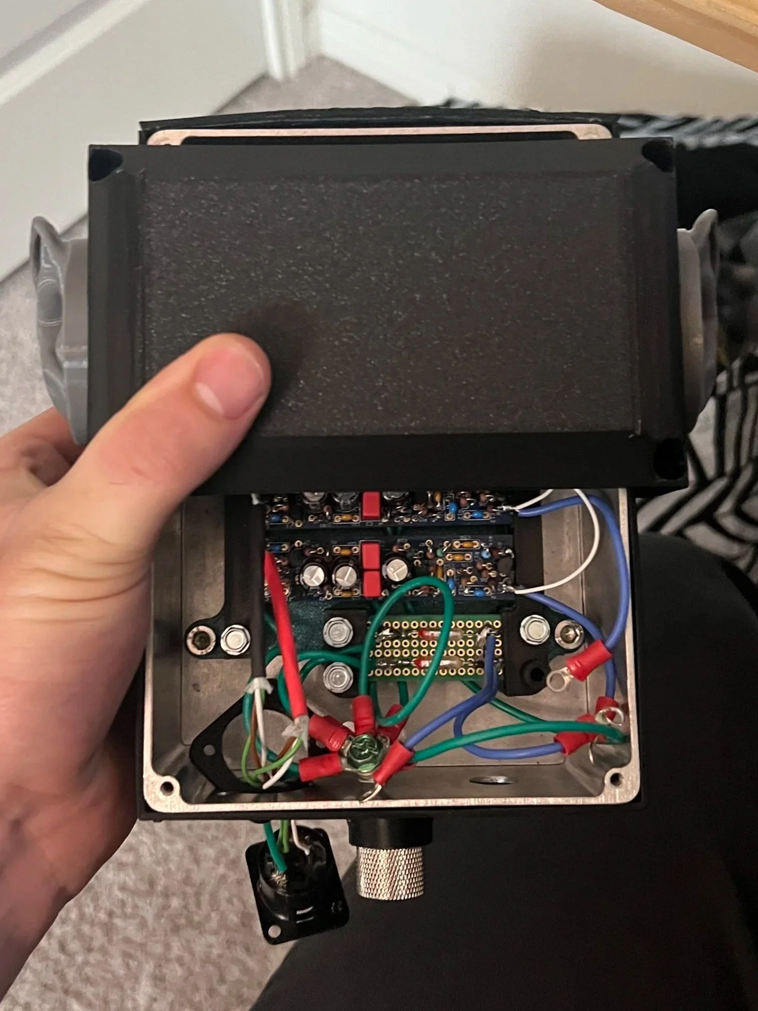
Grounding
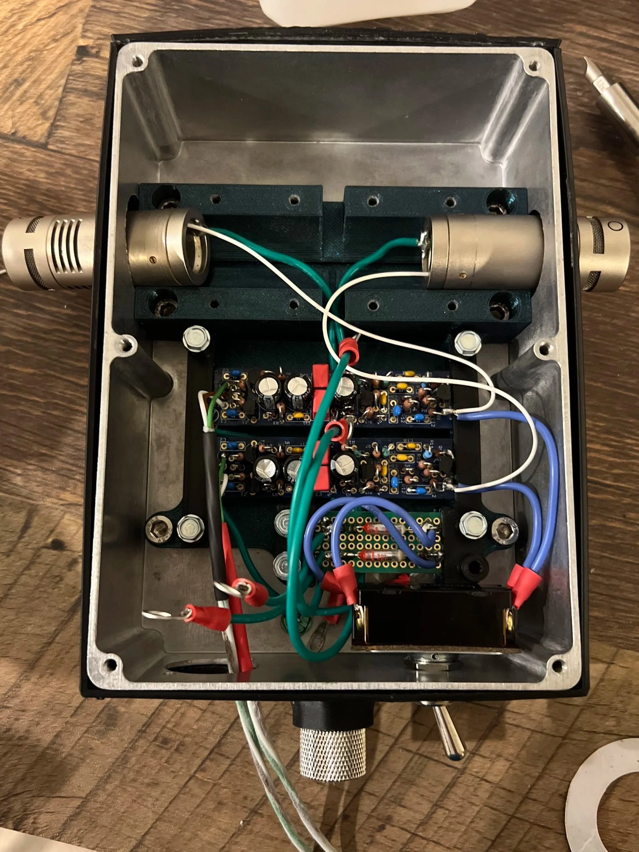
To ensure there are no ground loops and there is quality EMI protection, all of the metal bodies and PCB’s are grounded to the same bolt via the green cables. The 5 pin XLR connector on this microphone is also grounded to eliminate all potential EMI ingress points.
Assembly
While the KU 100 can be taken apart without tools my microphone requires 2 Allen keys and a screwdriver. each piece is bolted together with precise fitment using stainless steel hardware. this provides no risk of corrosion and strength throughout the microphone.
Stereo Output
like the KU 100 this dummy head is wired with a 5 pin stereo XLR which has a custom 5 to dual 3 pin stereo splitter. this is done to reduce the number of connectors on the bottom of the microphone.
Mic Body Modifications
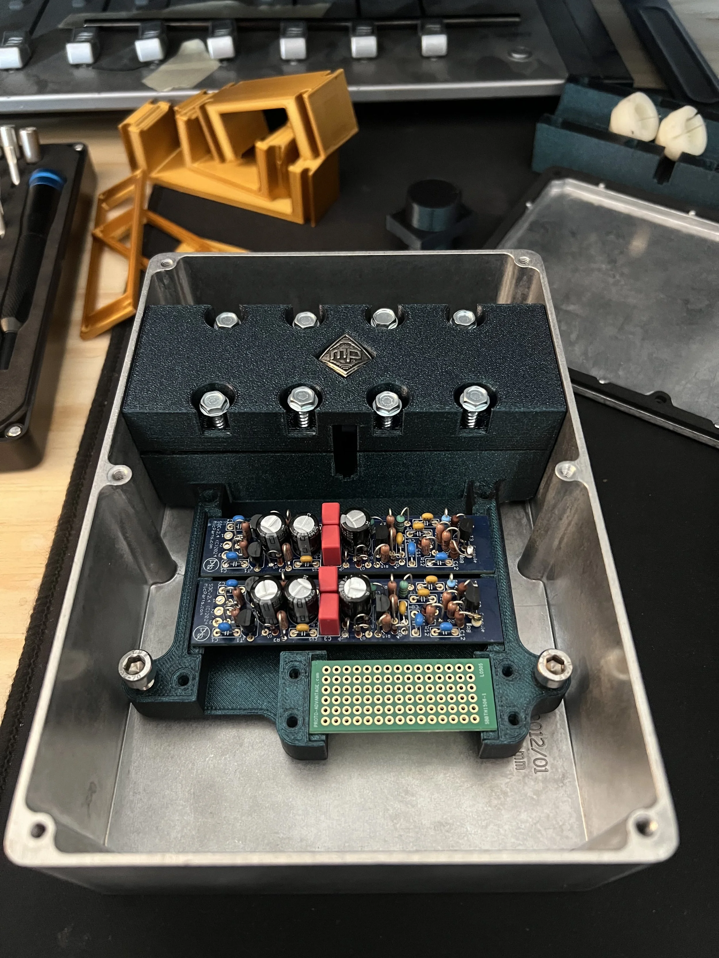
the distance between the 2 ear assembly is 138 mm.. the length of one SDC pencil condenser is also 138 mm. to fit the components inside of this space each mic body was cut down to 56.6 mm and had the internals sized to hold the nosecone the right distance from the capsule. this length gives us just enough space to fit both capsules using original hardware which helps to keep the signal wire shielded. I was able to retain the same set screw mounts for the end cap by using a 3D printed jig to guide the drill. by doing this and connecting a ground cable directly to the mic body (for EMI protection) I was able to fit both microphones between the ears with ~36 mm of extra space for the ear canal modifications,
Mounting
A standard microphone thread is 5/8-27. This is a very unique thread that isn’t commonly used anywhere else. because of this there was no off the shelf hardware that I could purchase for this microphone. To get around this issue I embedded a 3/8-16 nut into the bottom of the case and use a 3/8-16 to 5/8-27 adapter to mount it. This isn’t the only mount in the microphone though. opposite the 3/8-16 nut on top of the box is an embedded 1/4-20 nut. this is the standard attachment for a camera system. with a short extender to reach the Toal head height this mount can be used with any camera equipment. its primary intent is for a 360 degree camera to allow for fully immersive video and audio to be recorded at the same time.
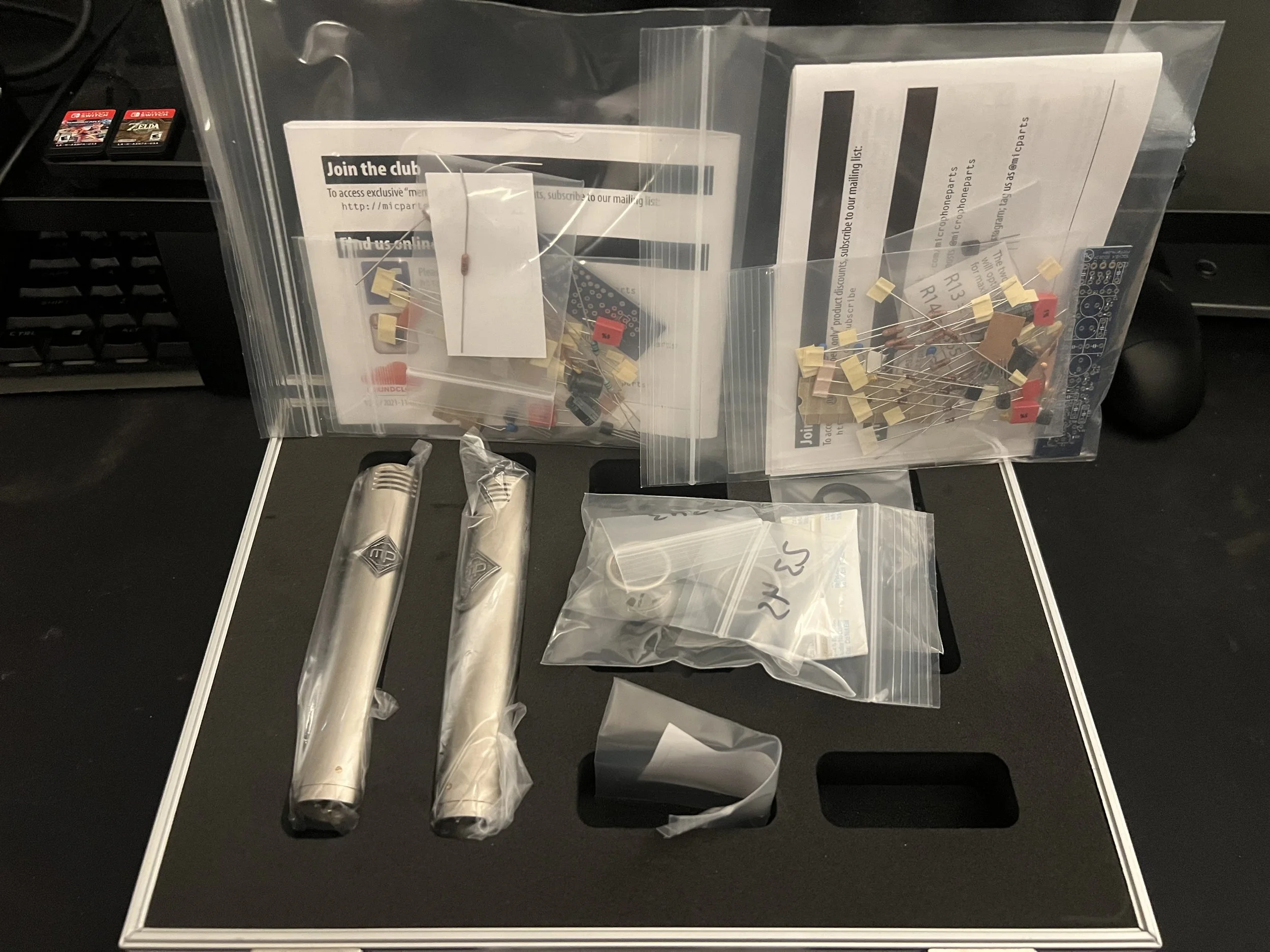
Micparts SDC kit
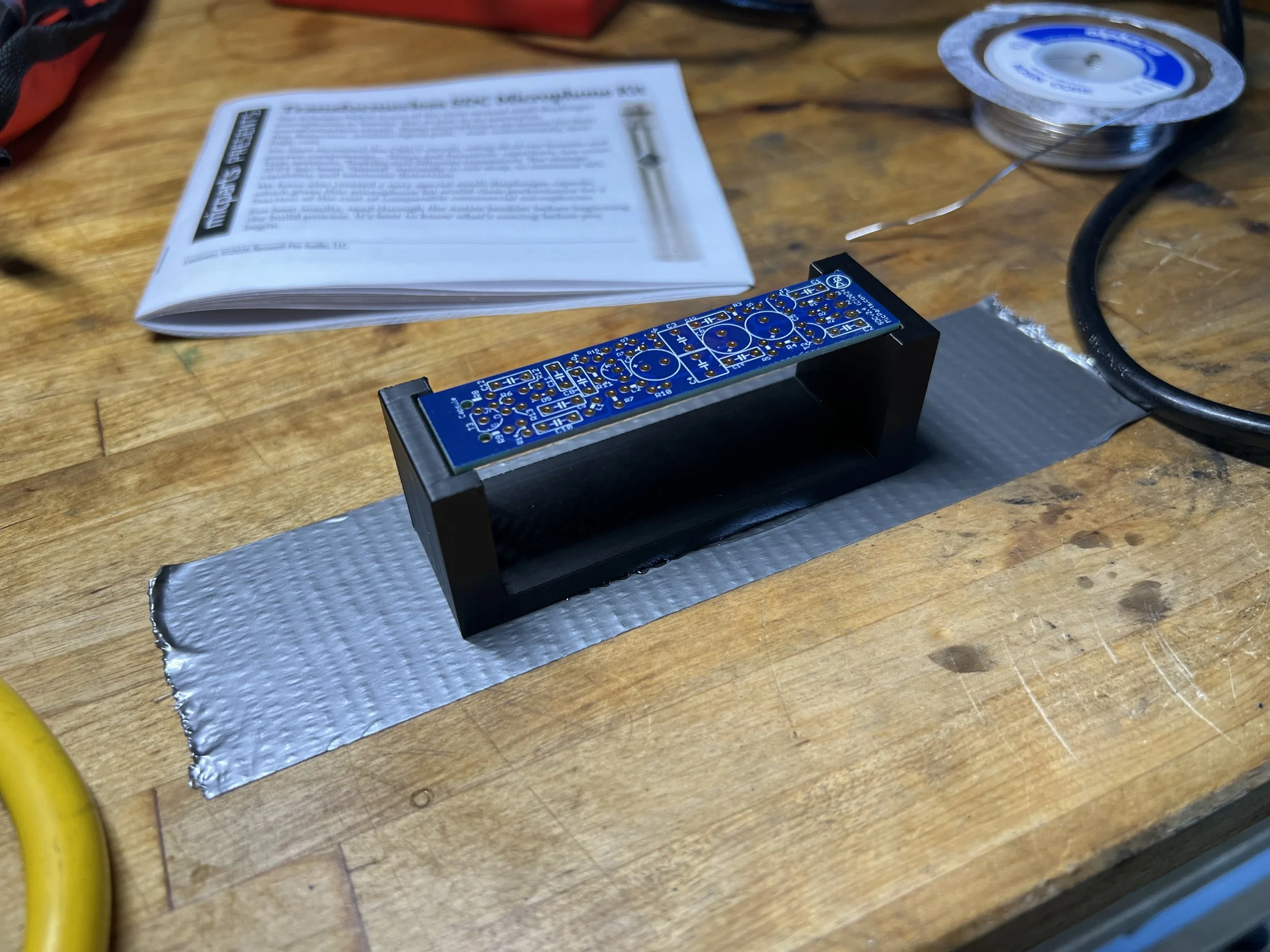
Mic internal preamp PCB bare
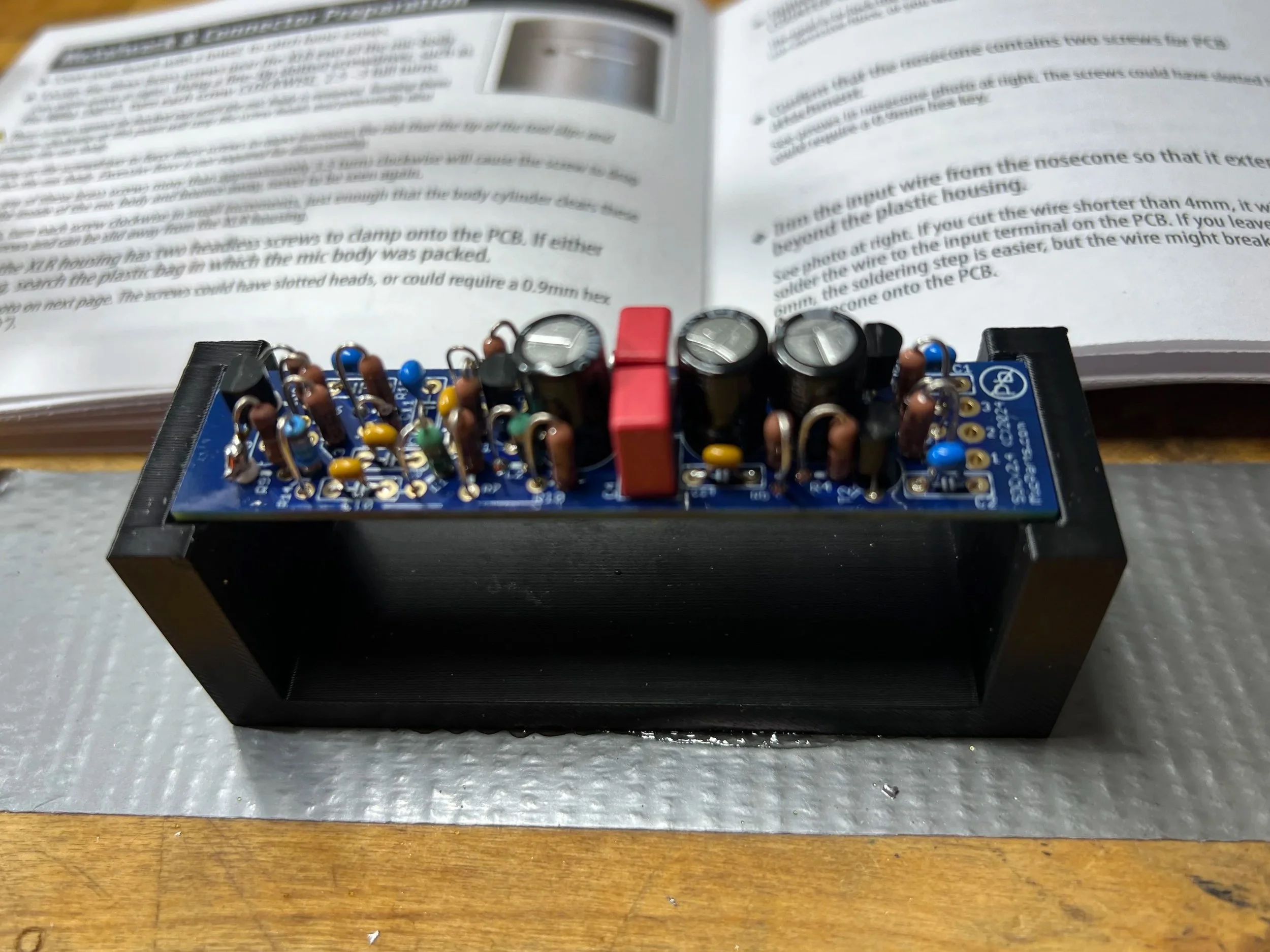
Mic internal PCB complete
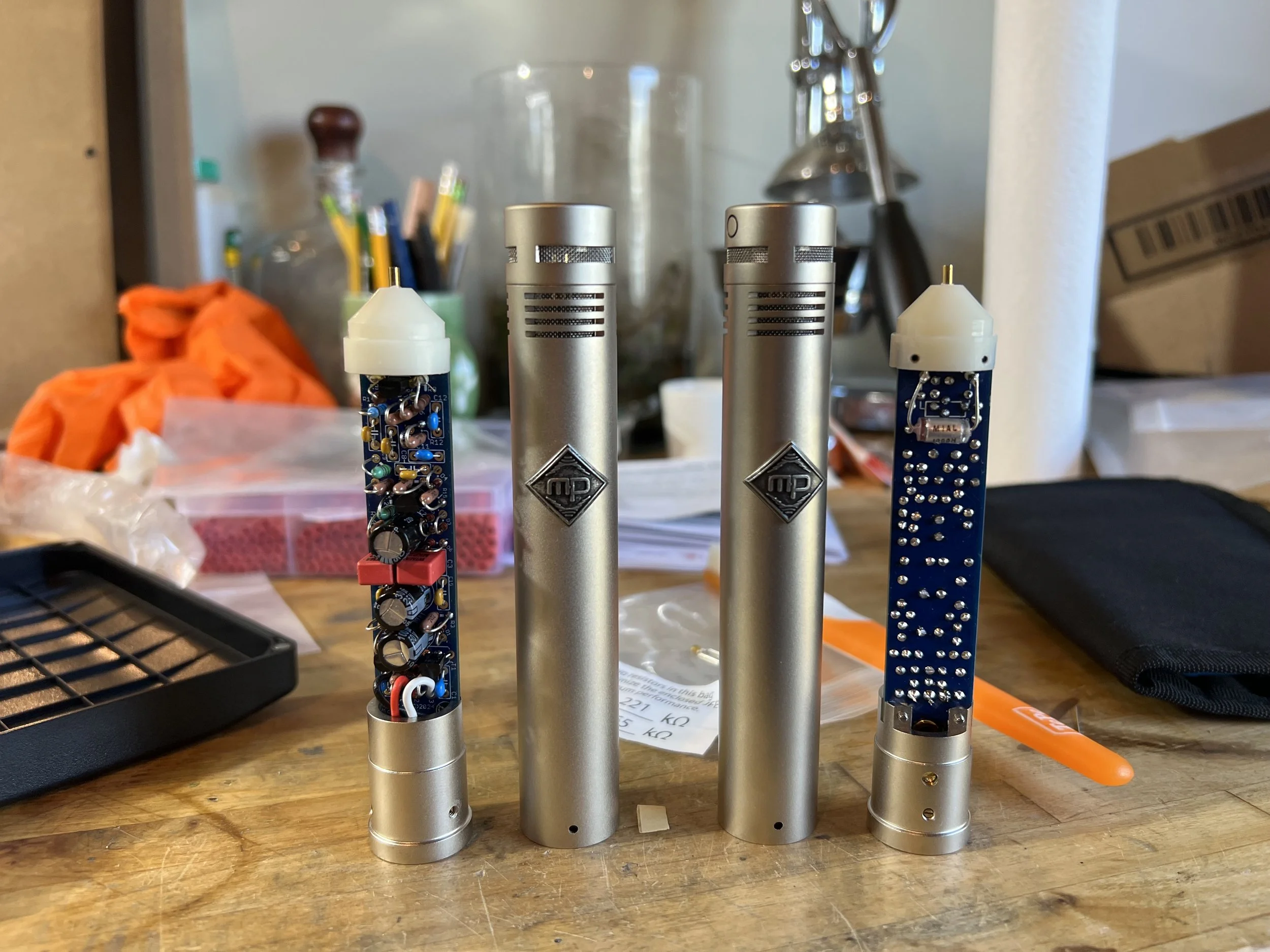
Functioning Mic Parts pencil condensers
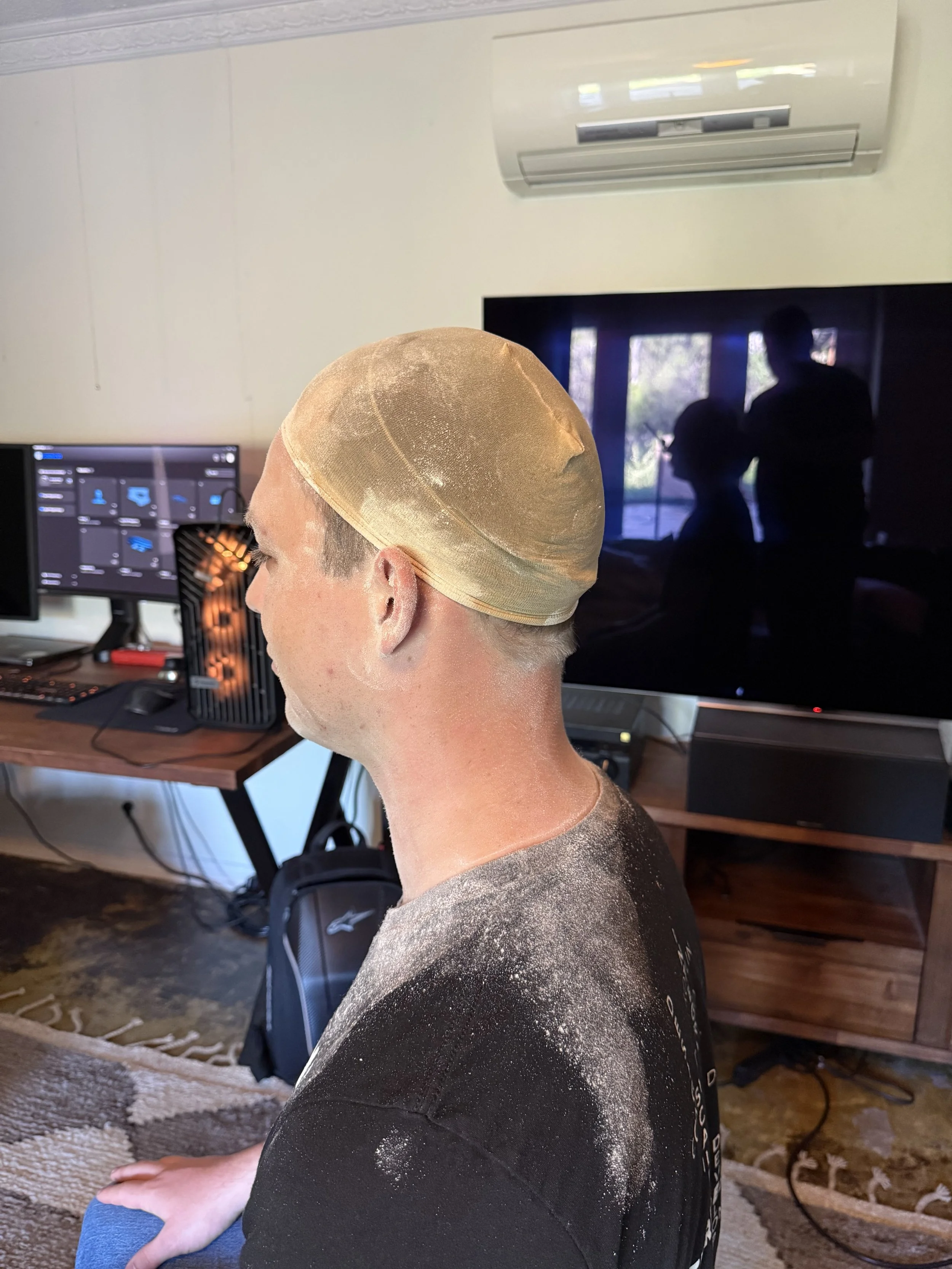
prep for 3D head scan
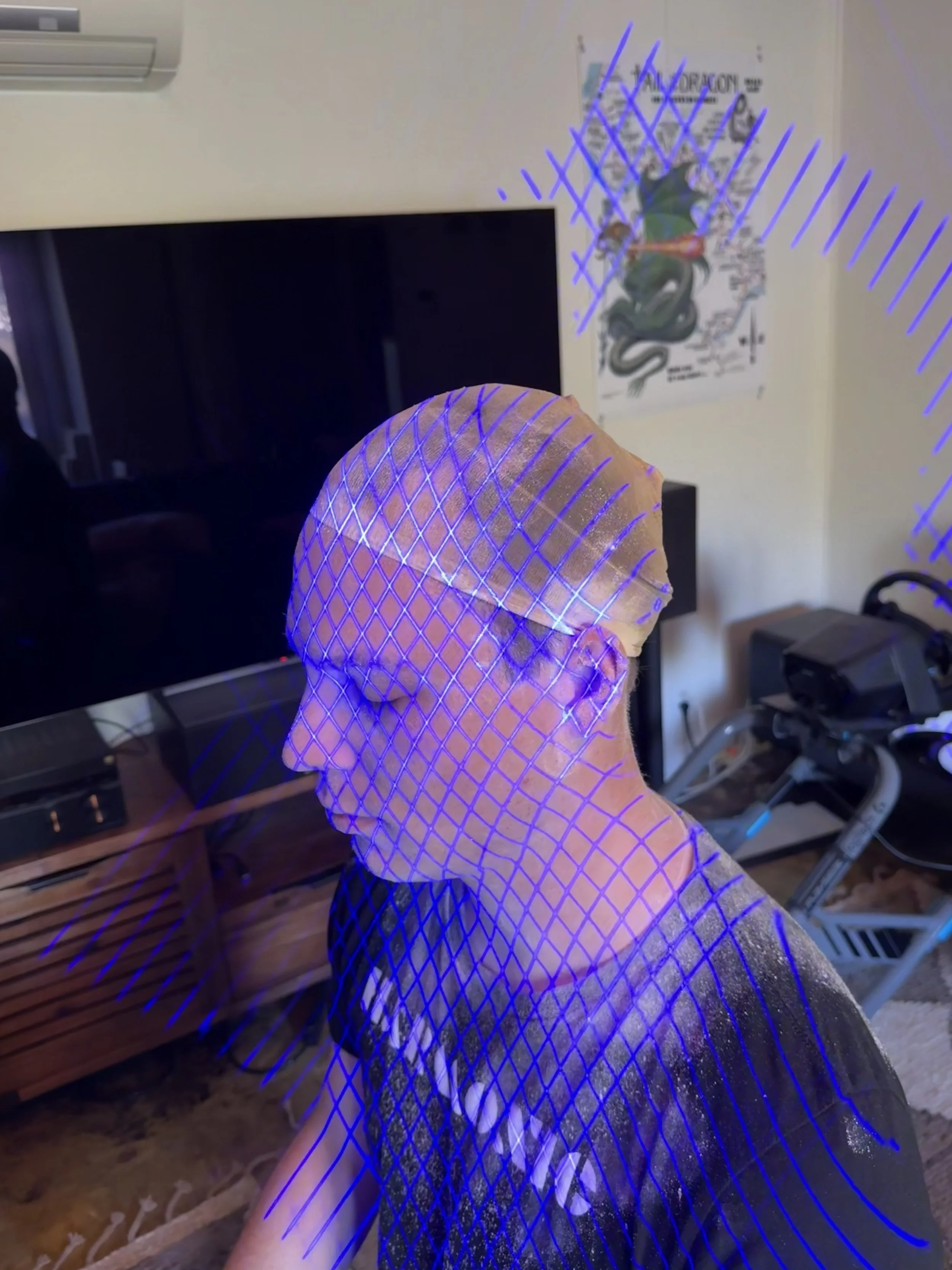
3D scan of head
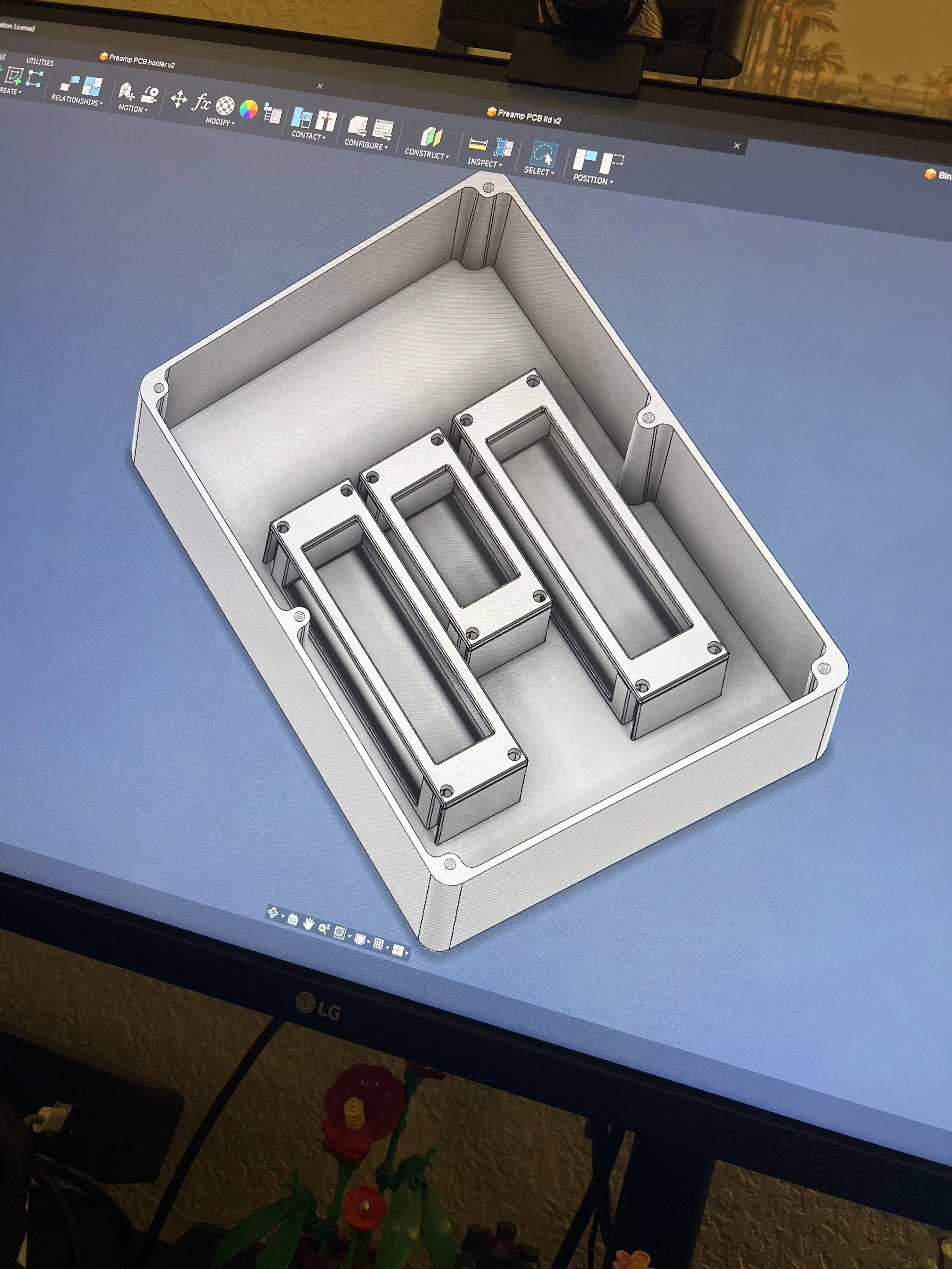
Cad assembly of microphone 1/3
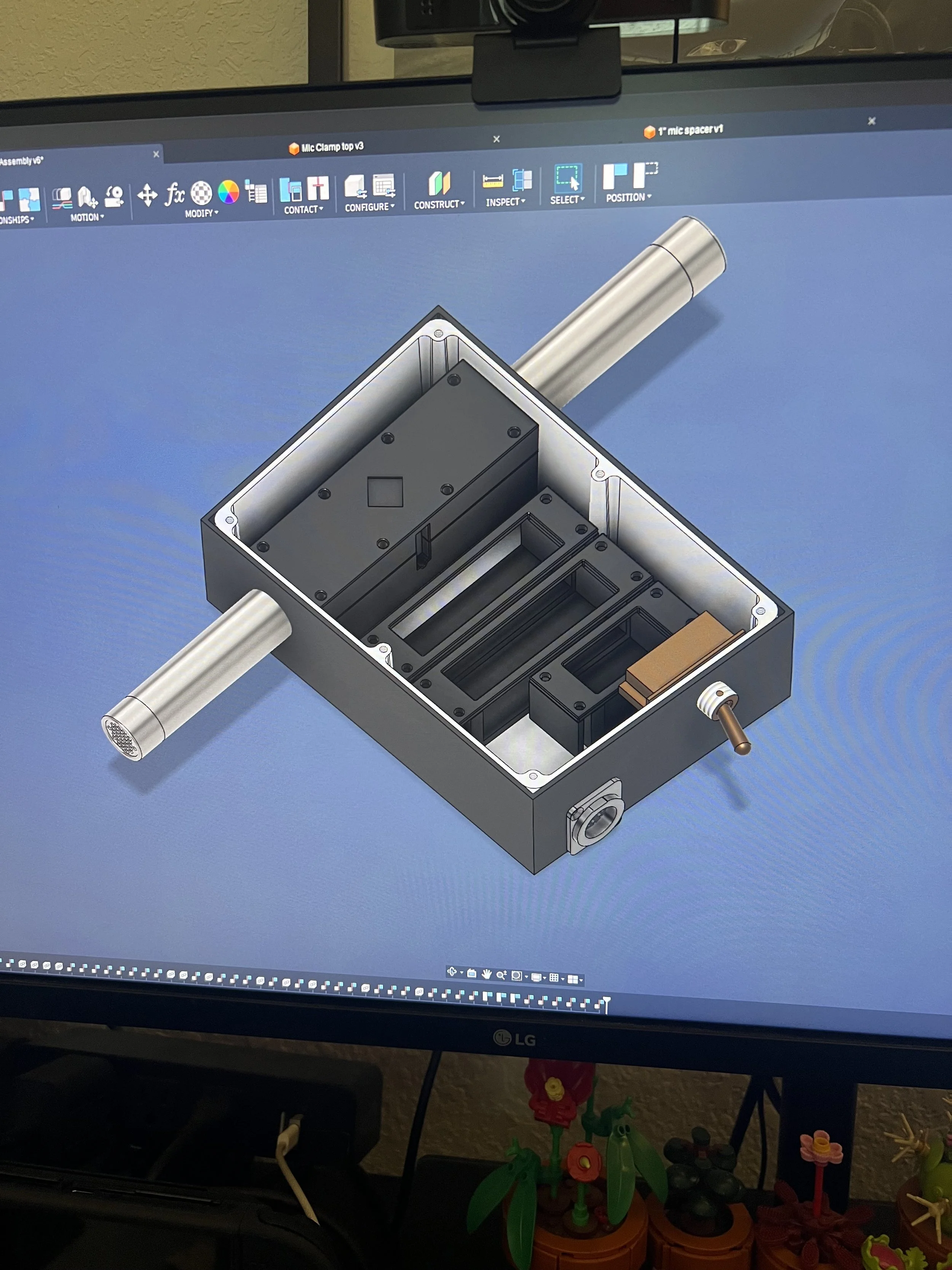
Cad assembly of microphone 2/3
Cad assembly of microphone 3/3
Test fit of microphone components 1/2
Test fit of microphone components 2/2

Shortening of mic bodies
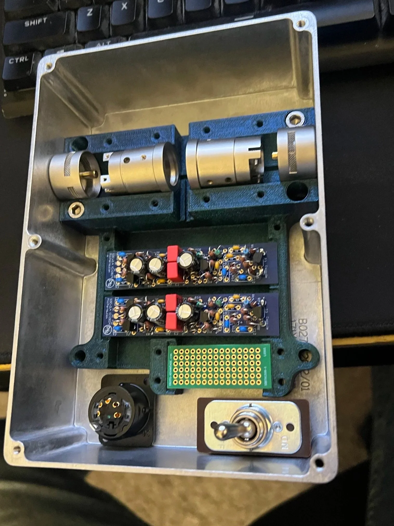
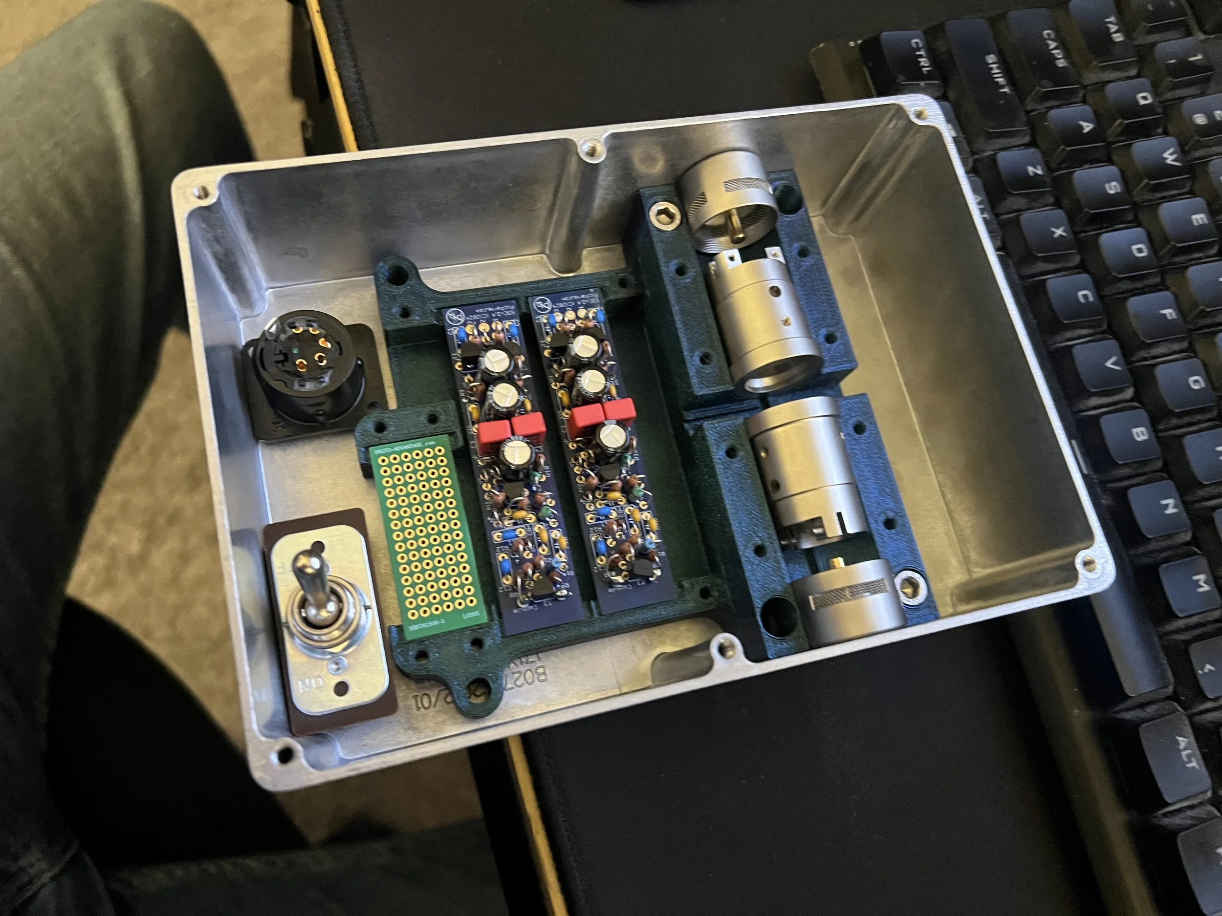
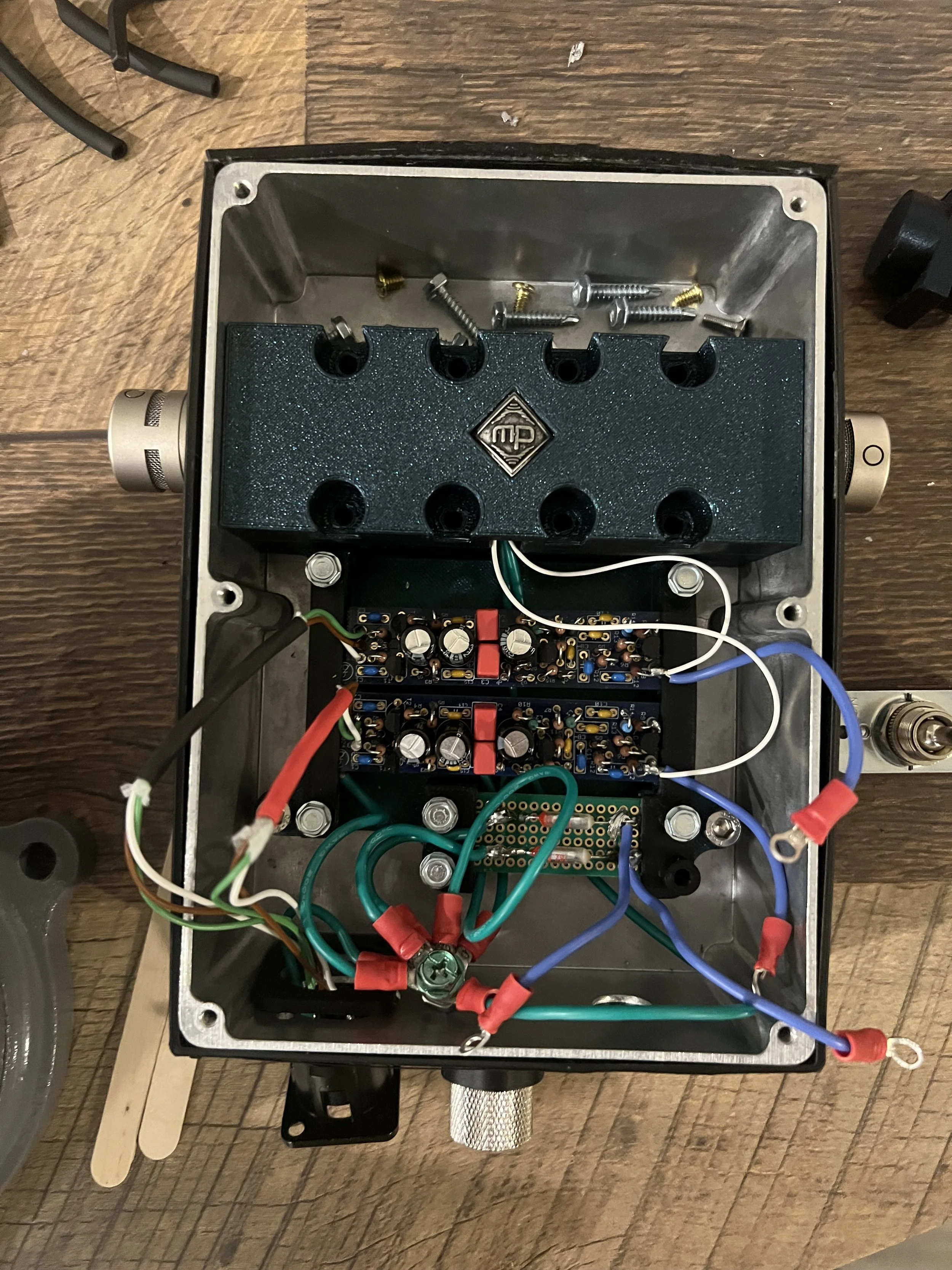
Assembly of all internal components
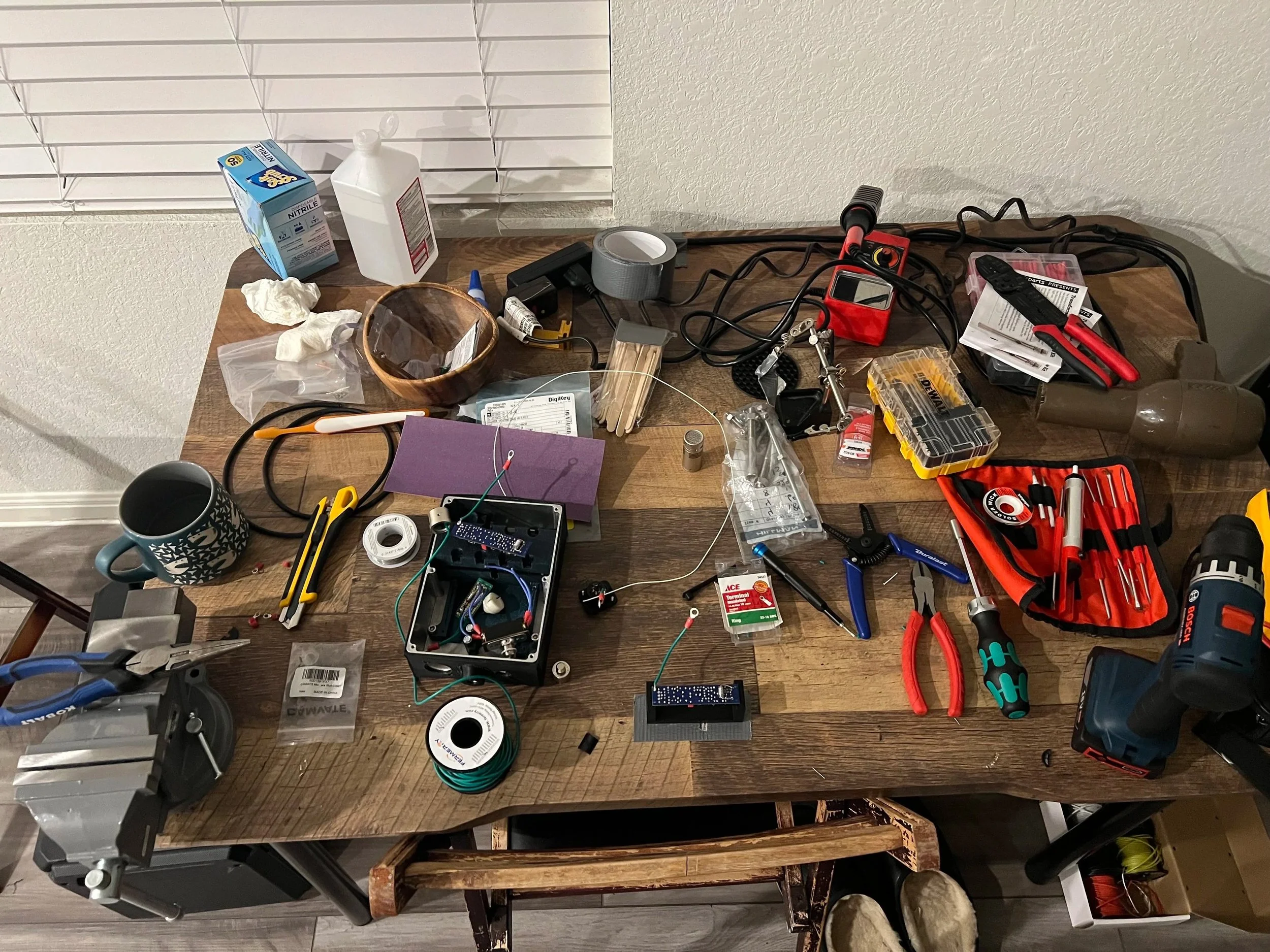
Wiring station for microphone
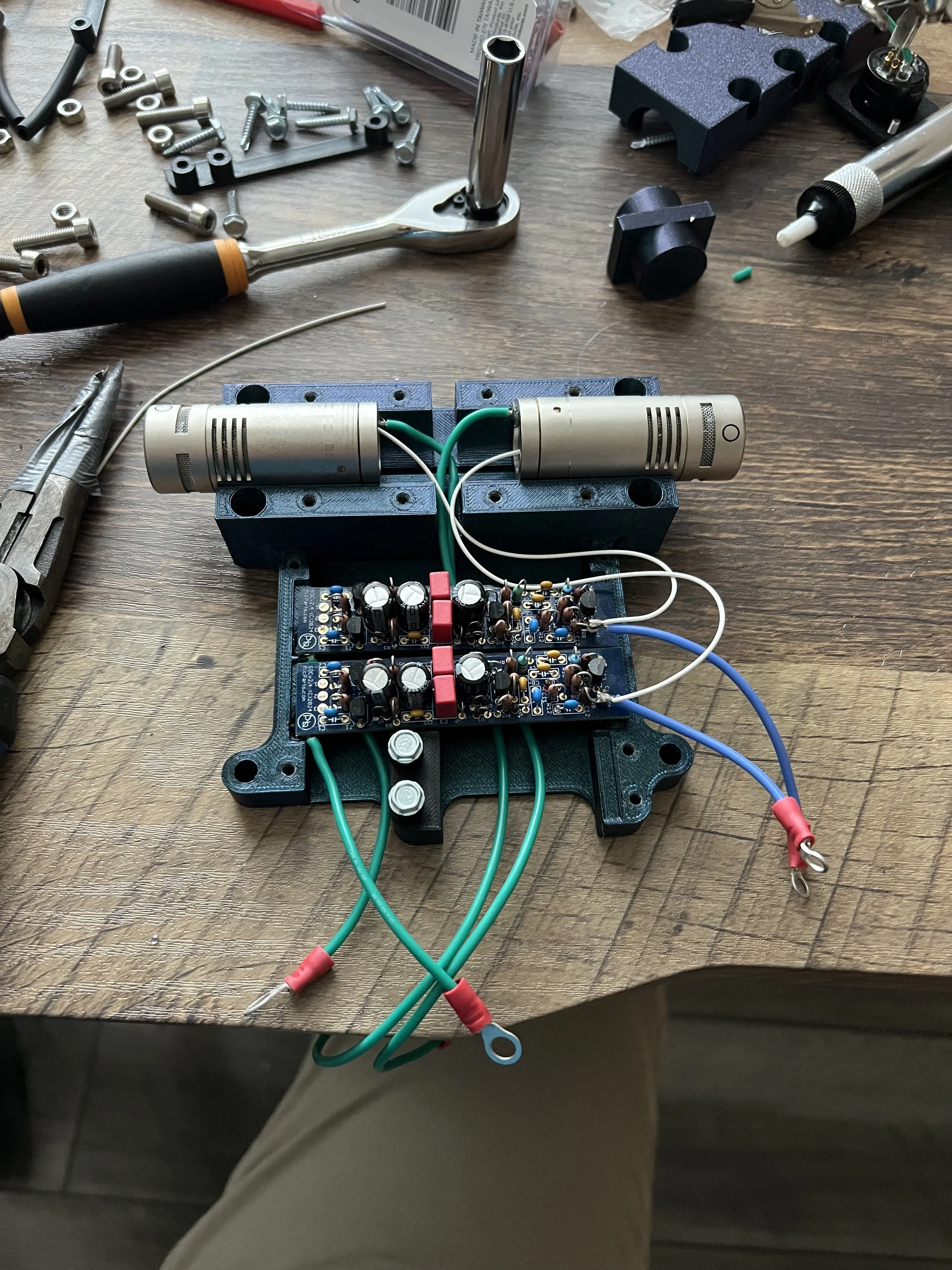
Wiring microphone components 1/4
Wiring microphone components 2/4
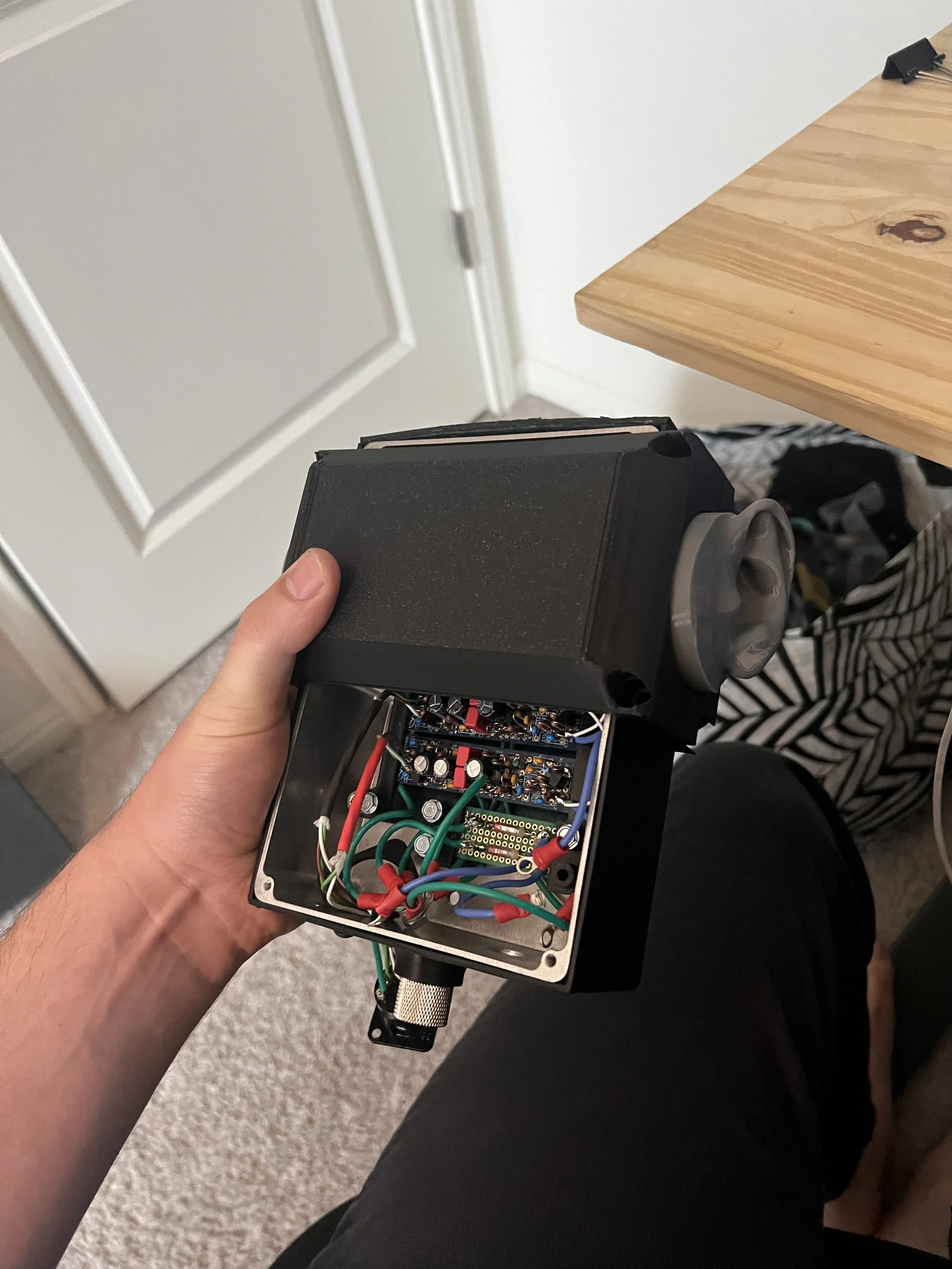
Wiring microphone components 3/4
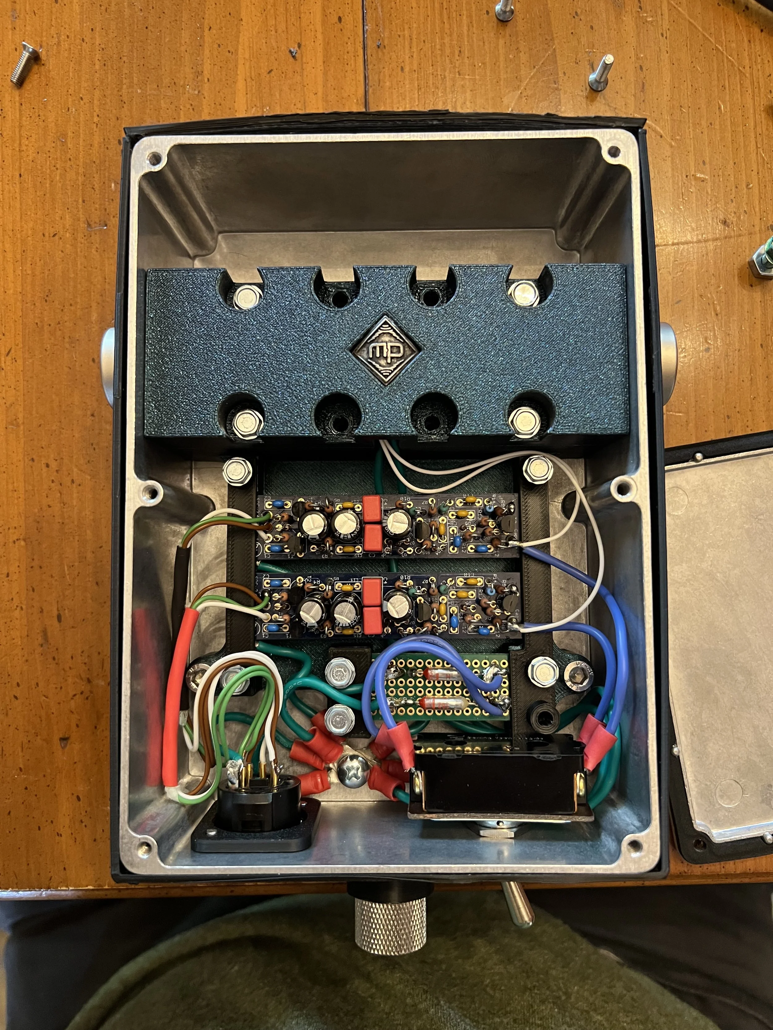
Wiring microphone components 4/4
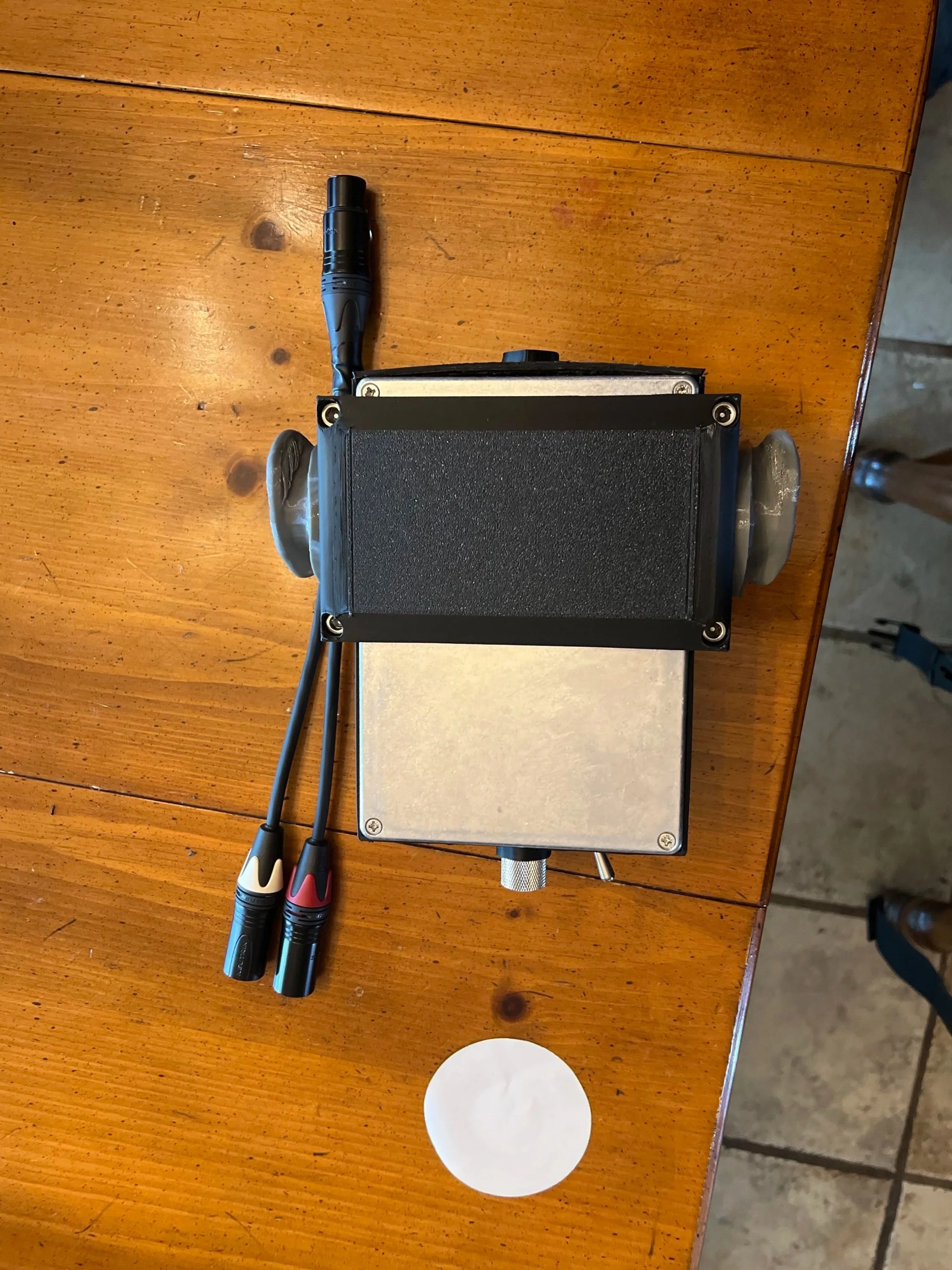
Core assembly complete
Creating head encasement
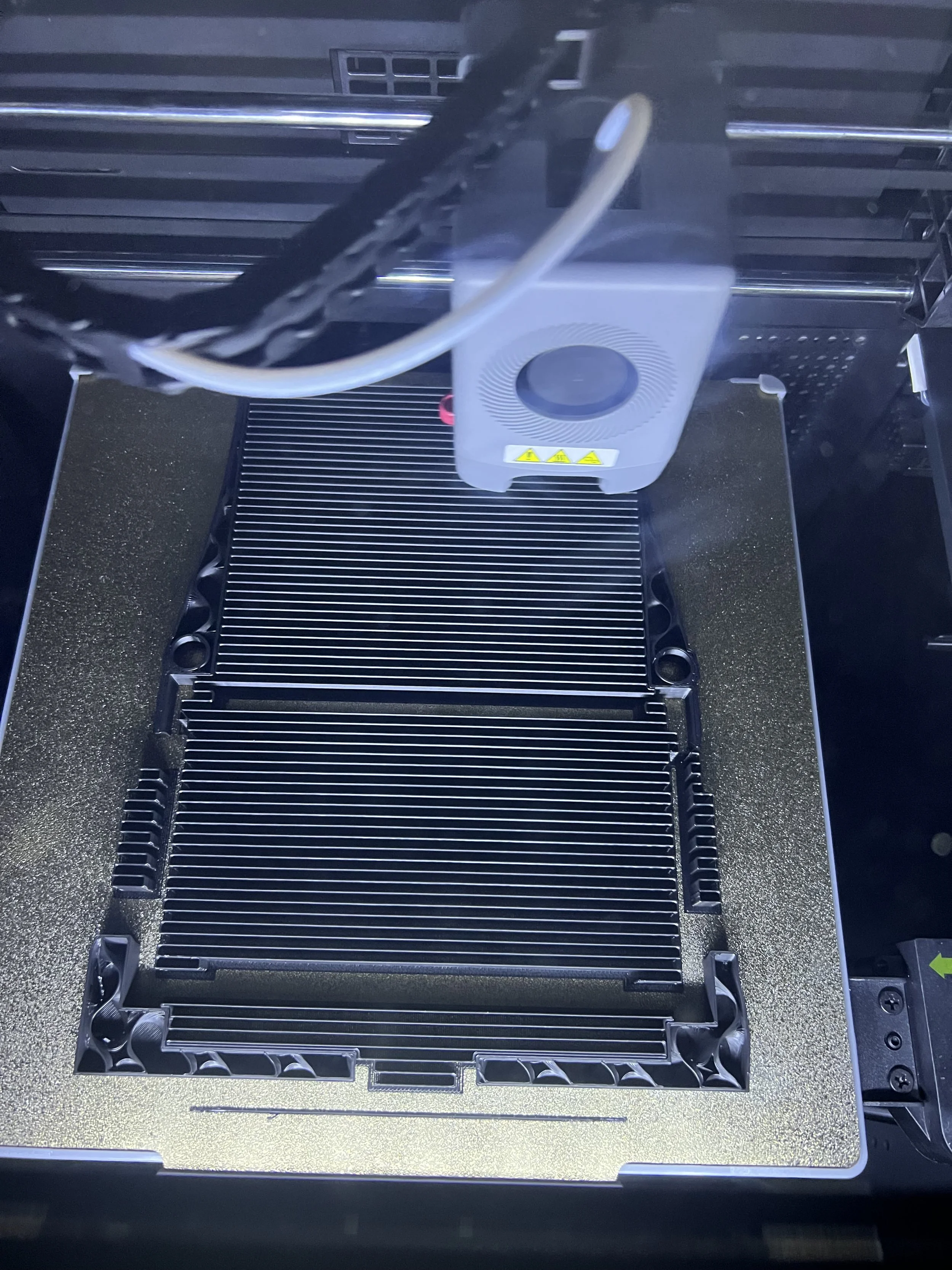
3D printing head shell 1/6
3D printing head shell 2/6
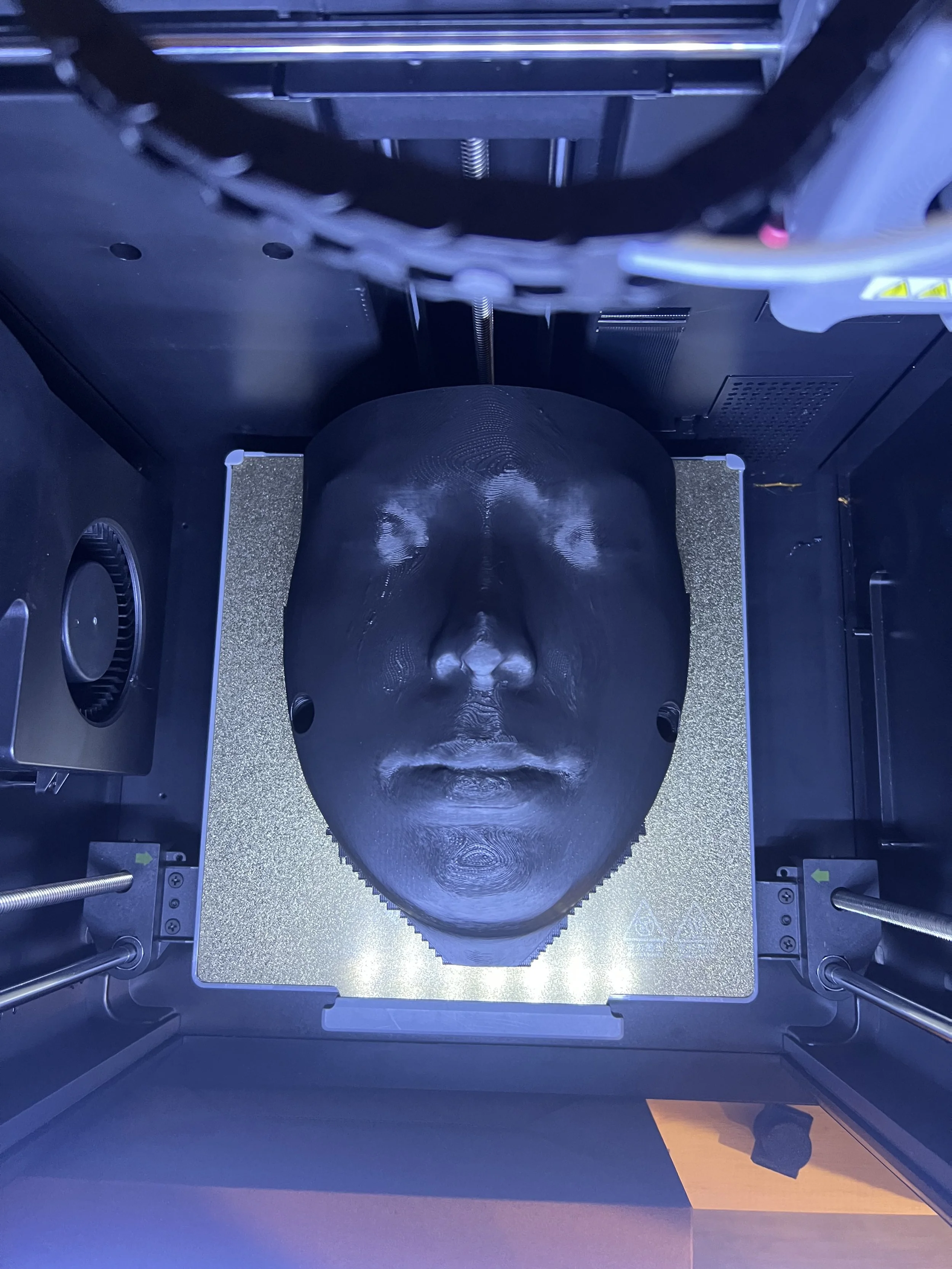
3D printing head shell 3/6
3D printing head shell 4/6
3D printing head shell 5/6
3D printing head shell 6/6
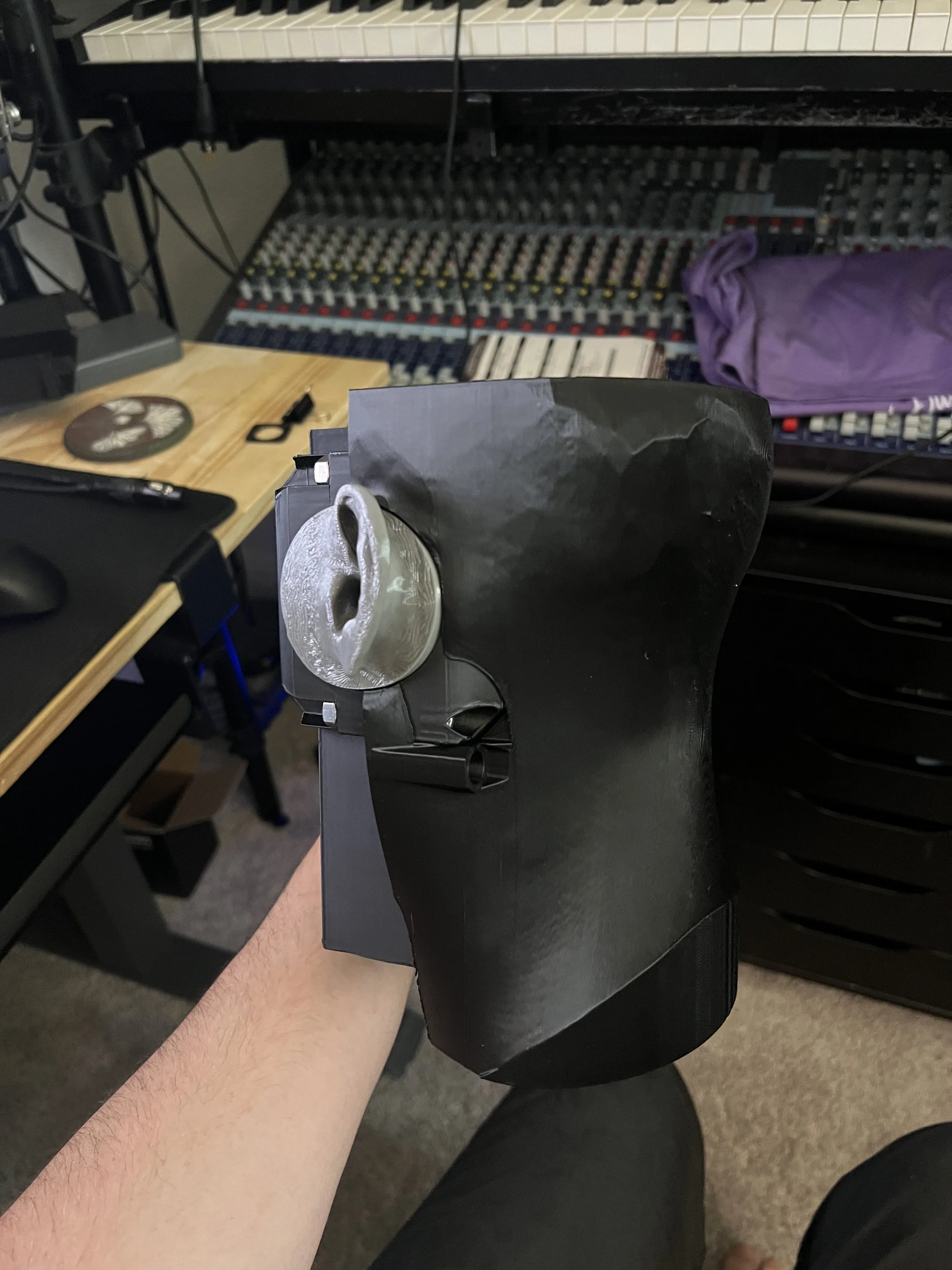
Modification of ear canals
Internal noise reduction
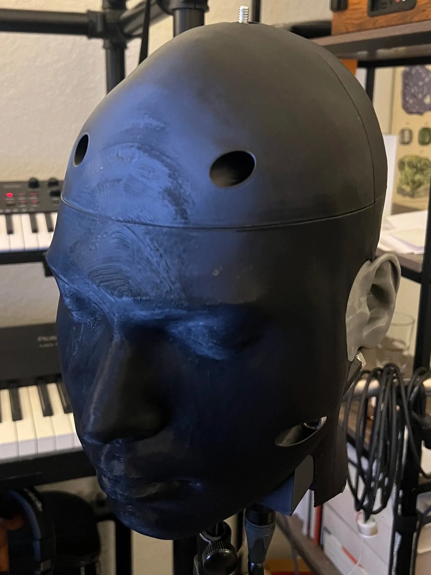
Final assembly
Troubleshooting
When the Microphone was first completed there a couple of different issues. First, there was a large amount of EMI and electrical noise. Secondly, the microphones were very susceptible to air movement and would clip the internal preamps. Finally, the frequency response and stereo imaging was rather poor and the microphone sounded boxy.
Solving the EMI: with some testing the EMI was caused by 2 sources. 1 the initial preamps and cables were creating massive amount of noise and problems. and 2 the signal wires from the capsule to the preamp were running next to a high voltage inductor which was emitting high pitched frequency sweeps. to remedy this I taped the cables in a new position and added a plastic shield. in the future I would like to install a grounds metal barrier between the signal wires and the internal preamps.
Solving the sensitivity and EQ: The other two issues were resolved with the addition of 2 pieces. First a 2mm thick piece of 40 ppi open cell polyurethane foam as added into the ear to reduce air movement without harming acoustics. and a 18mm hollow cone (Based off of Stephan Peus’s paper) was added to make the sure the 7.5mm ear canal air was evenly dispersed across the 22mm microphone capsule. by adding these two components the frequency response became nearly flat (~ -3db shelf starting at ~3.5Khz) and the microphones sensitivity to air was removed.
Solving the stereo imaging: the improvements to the ear canal greatly improved the stereo imaging of the microphone. However, the height was translating incorrectly. I found this phenomenon in Stephan Peus’s writing that since the ears are aligned correctly to the head upon playback you perceive everything tilted upwards. the solution to this is to angle the ears slightly downwards to counteract this effect.
Compromises and updates
Due to the timeline of this build I had to make a couple different compromises. the most notable of which are the lack of any HPF’s and the internal battery. the smaller compromises are that of material choice such as silicone casting the ears and a shell for the head.
For a Version 2 of this head there is a short list of updates I would make.
have an internal power supply
learn to modify the preamps to add switchable HPF’s
silicone cast the ears and add a 2mm silicone skin
reduce the size of the internal components so they don’t stick out as much
fully shielded signal wires from the capsule to the PCB
find a more consistent 3D model of a head
EQ testing and adjustment
by making these 6 update the microphone would be far more polished. despite these compromises the current microphone still works wonderfully and I am able to get by without the HPF or the internal battery supply by using boards, external phantom power devices, and digital EQ’s.
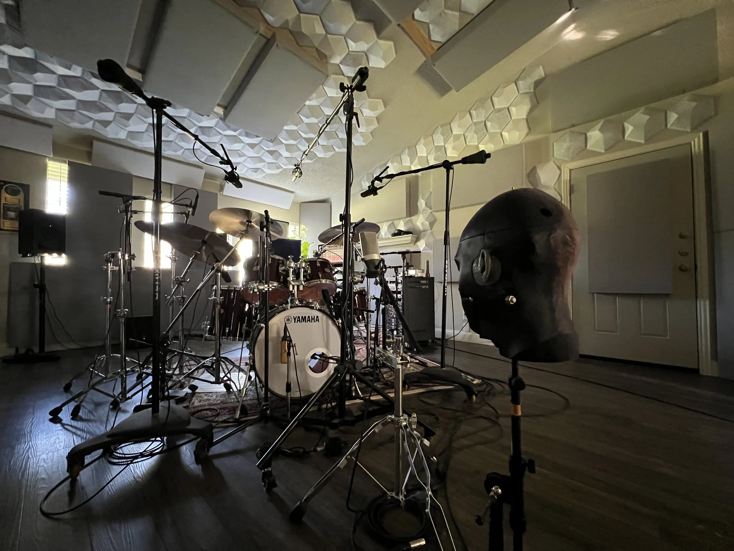
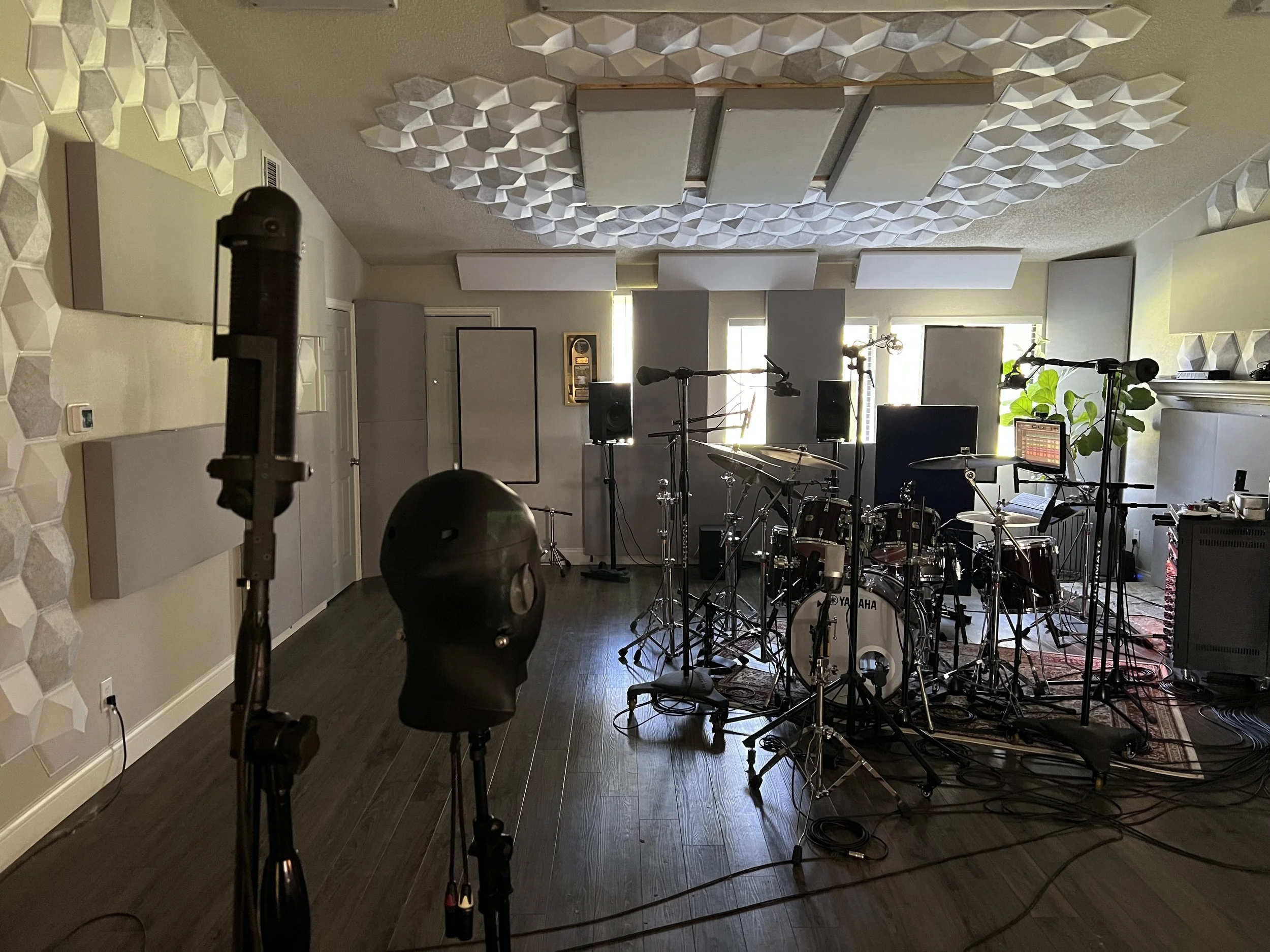
Testing and observations
The microphone was tested in a studio environment using a drum set as the sound source.
Compared to the other stereo recording the Binaural head has a much wider and more precise stereo image. This makes it feel roomier, however, despite it feeling roomier it captures the tone of the room much more realistically which means very short reverb tails and a very dry sound in the studio. It is the closest reproduction of my ears that I have heard from a microphone.
there was a noticeable tilt in the height of everything. the ears need to be adjusted as was mentioned in the troubleshooting section. currently everything sits about 5 degrees to high.
The microphone definitely has a color and a character. It is not perfectly flat. it has very crisp and clear mid and lows. with decent high mids. The mic doesn’t feel as open because of a notch around 17Khz created from the physical shape. this can be corrected using a digital EQ. Some of the boxy feel is also from how dry the microphone sounds.
Overall, This microphone works exactly as intended. able to record high volume sources (8 inches away from a kick drum) with no distortion super precise 3D imaging and an accurate capture of the room. With a few modifications and tweaks I think it can sound even better.
R88 blumlein room mic for comparison
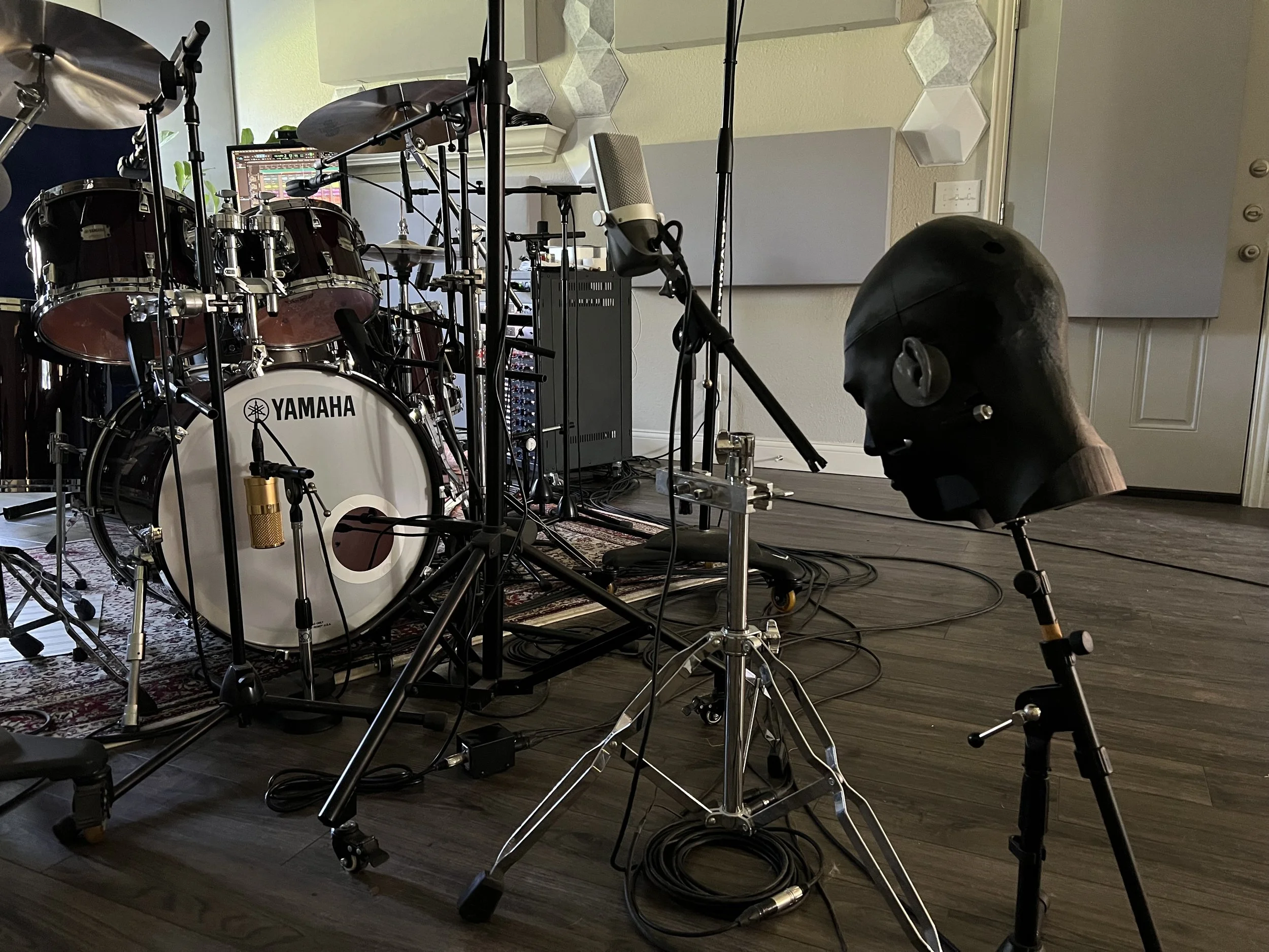
Dummy Head positioned as Room mic
Dummy Head positioned as overheads
Dummy Head positioned as the drummers head
Mono front of kit mic for comparison
Dummy Head positioned as a front of kit mic
Dummy Head front of kit angled upwards
Dummy Head front of kit angled downwards
3D audio test before troubleshooting EMI and EQ
3D audio test post troubleshooting EMI and EQ
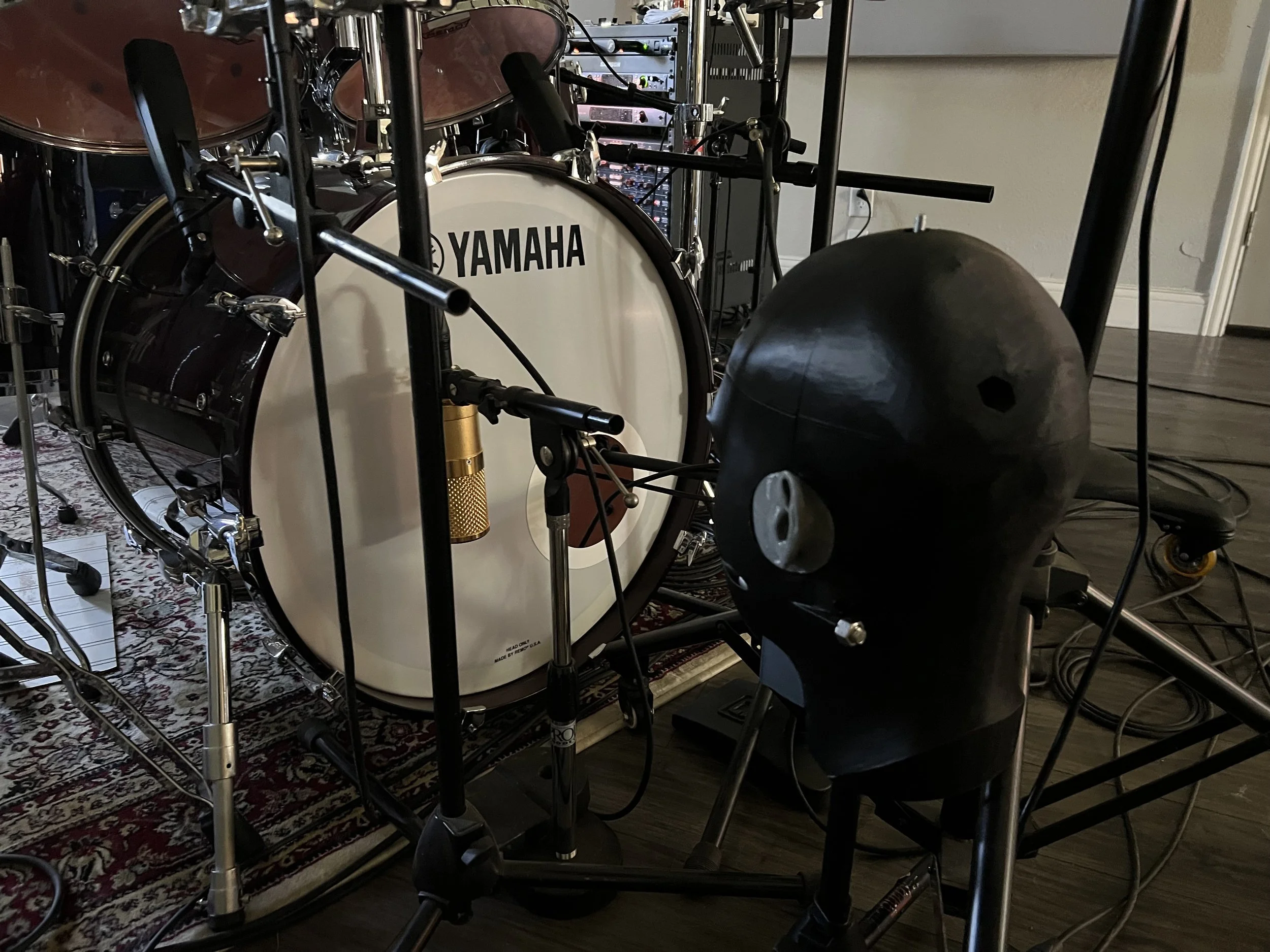
Dummy Head positioned as a kick mic
Kick mic for comparison
Research sources and Documents
KU 100 Operating instructions:
https://www.bhphotovideo.com/lit_files/924734.pdf
Stephan Peus’s writings:
https://funkwerkes.com/web/wp-content/techdocs/MixedProAudio/Microphones-Transients.pdf
Stephan Peus Interview:
https://newsroom.neumann.com/the-man-behind-the-neumann-ku-100-dufytw
https://www.proaudio.tech/news/recording/interview-the-man-behind-the-neumann-ku-100
KU 100 Partial Disassembly:
Research paper on optimal windscreen foam density
Blog on Building DIY Binaural mics:
Japanese submission for model of an artificial ear IEC 60318:
https://iopscience.iop.org/article/10.1088/0026-1394/45/4/011#skip-to-content-link-target
https://iopscience.iop.org/article/10.1088/0026-1394/49/6/785
3D model like Japanese submission IEC 60318:
https://grabcad.com/library/ear-model-like-iec-of-the-japan-proposal-1
Handbook for Sound engineers fourth edition chapters: 16, 22, and 23